Блок Двигателя Разборка. Corolla Auris
Двигатель. COROLLA, AURIS. ZZE150 ZRE151,152 NDE150
REMOVE NOZZLE HOLDER SEAL
REMOVE OIL FILLER CAP
REMOVE CYLINDER HEAD COVER SUB-ASSEMBLY
REMOVE NO. 1 NOZZLE LEAKAGE PIPE ASSEMBLY
REMOVE INJECTOR ASSEMBLY
REMOVE NOZZLE HOLDER CLAMP SEAT
REMOVE NO. 2 OIL PAN SUB-ASSEMBLY
REMOVE OIL FILTER CAP ASSEMBLY
REMOVE OIL FILTER ELEMENT
REMOVE OIL FILTER BRACKET
REMOVE OIL STRAINER SUB-ASSEMBLY
REMOVE CRANKSHAFT PULLEY
REMOVE WATER PUMP ASSEMBLY
REMOVE TIMING CHAIN COVER SUB-ASSEMBLY
REMOVE NO. 1 CHAIN TENSIONER ASSEMBLY
REMOVE CHAIN TENSIONER SLIPPER
REMOVE NO. 1 CHAIN VIBRATION DAMPER
REMOVE CAMSHAFT TIMING SPROCKET
REMOVE NO. 1 CAMSHAFT
REMOVE VALVE ROCKER ARM SUB-ASSEMBLY
REMOVE VALVE LASH ADJUSTER ASSEMBLY
REMOVE CYLINDER HEAD SUB-ASSEMBLY
REMOVE OIL PAN BAFFLE PLATE
CLEAN CYLINDER BLOCK SUB-ASSEMBLY
Блок Двигателя -- Разборка |
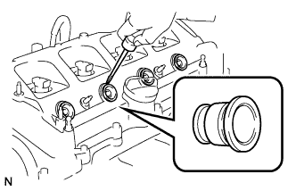
| 1. REMOVE NOZZLE HOLDER SEAL |
Using a screwdriver, pry out the 4 nozzle holder seals.
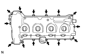
| 3. REMOVE CYLINDER HEAD COVER SUB-ASSEMBLY |
Remove the 2 nuts, 2 washers, 12 bolts, cylinder head cover and cylinder head cover gasket.
- ПРИМЕЧАНИЕ:
- When removing the cylinder head cover from the cylinder head, do not allow the injectors to damage the nozzle holder gasket.
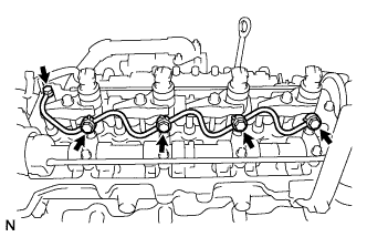
| 4. REMOVE NO. 1 NOZZLE LEAKAGE PIPE ASSEMBLY |
Remove the 5 union bolts, nozzle leakage pipe and 5 gaskets.
- ПРИМЕЧАНИЕ:
- When removing the nozzle leakage pipe, place a shop rag or a piece of cloth under the pipe to protect the cylinder head from the fuel remaining inside the pipe.
| 5. REMOVE INJECTOR ASSEMBLY |
Remove the 4 bolts, 4 washers and 4 nozzle holder clamps.
Remove the 4 injectors from the cylinder head.
Remove the O-rings from each injector.
Remove the 4 nozzle seats from the cylinder head.
- УКАЗАНИЕ:
- When replacing the injector assemblies, store them in a correct order so that they can be returned to their original locations when being reassembled.
| 6. REMOVE NOZZLE HOLDER CLAMP SEAT |
Remove the 4 nozzle holder clamp seats.
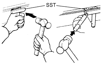
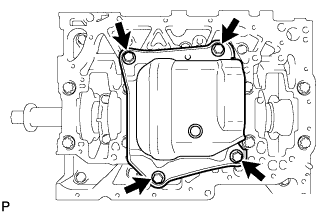
| 7. REMOVE NO. 2 OIL PAN SUB-ASSEMBLY |
Remove the drain plug and gasket.
Remove the 18 bolts and 2 nuts.
Insert the blade of SST between the oil pan and crankshaft bearing cap, cut through the applied sealer, and remove the oil pan.
- SST
- 09032-00100
- ПРИМЕЧАНИЕ:
- Do not use SST for the timing chain cover side.
- Be careful not to damage the contact surfaces of the oil pan.
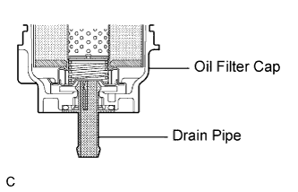
| 8. REMOVE OIL FILTER CAP ASSEMBLY |
Remove the oil filter drain plug and O-ring, then insert the drain pipe into the oil filter cap and drain the engine oil into a container.
- УКАЗАНИЕ:
- The drain pipe is supplied with the oil filter element.
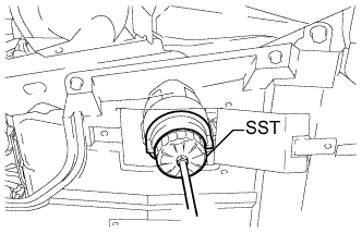
Using SST, remove the oil filter cap.
- SST
- 09228-06501
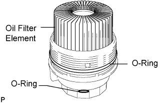
| 9. REMOVE OIL FILTER ELEMENT |
Remove the oil filter element and 2 O-rings from the oil filter cap.
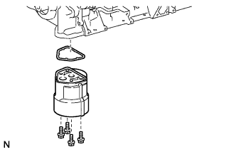
| 10. REMOVE OIL FILTER BRACKET |
Remove the 4 bolts, oil filter bracket, and gasket.
| 11. REMOVE OIL STRAINER SUB-ASSEMBLY |
Remove the 3 bolts, oil strainer, and O-ring.
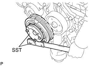
| 12. REMOVE CRANKSHAFT PULLEY |
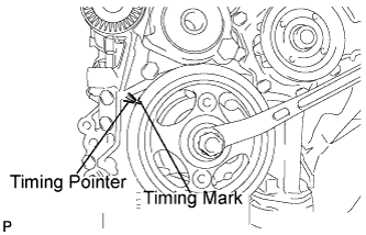
Set the No. 1 piston to TDC/compression.
Turn the crankshaft pulley clockwise to align the timing pointer of the timing chain cover and timing mark on the pulley.
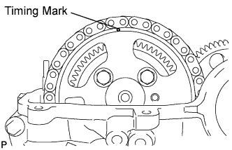
Make sure that the timing mark is at the top of the camshaft timing sprocket.
If not, turn the crankshaft 1 revolution (360°) and align the mark as described above.
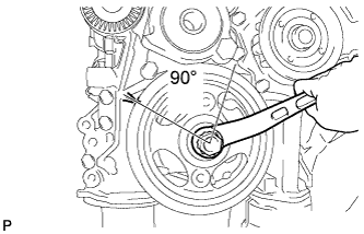
Turn the crankshaft by approximately 90° in the engine revolution direction at the point where the No. 1 piston is set to TDC/compression so that the lifted valve and piston do not contact each other when removing the camshaft.
Using SST, remove the pulley bolt.
- SST
- 09213-58013
09330-00021
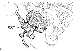
Insert the service bolt.
- Recommended service bolt:
Item
| Specified Condition
|
Thread diameter
| 8.0 mm (0.315 in.)
|
Thread pitch
| 1.25 mm (0.0492 in.)
|
Bolt length
| Approx. 30 to 38 mm (1.18 to 1.50 in.)
|
Using SST, remove the crankshaft pulley.
- SST
- 09950-50013(09951-05010,09952-05010,09953-05020,09954-05021)
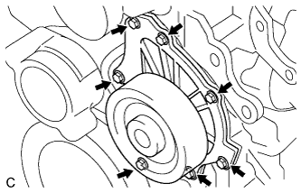
| 13. REMOVE WATER PUMP ASSEMBLY |
Remove the 7 bolts, water pump and gasket.
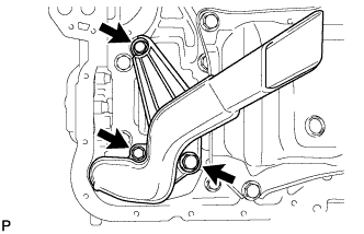
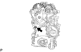
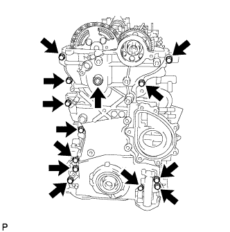
| 14. REMOVE TIMING CHAIN COVER SUB-ASSEMBLY |
Using a 10 mm socket hexagon wrench, remove the timing chain cover tight plug and gasket.
Remove the 13 bolts and seal washer as shown in the illustration.
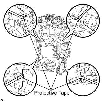
Remove the timing chain cover by prying between the timing chain cover and cylinder head or cylinder block with a screwdriver.
- УКАЗАНИЕ:
- Tape the screwdriver tip before use.
- ПРИМЕЧАНИЕ:
- Do not damage the contact surfaces of the cylinder head, cylinder block, and timing chain cover.
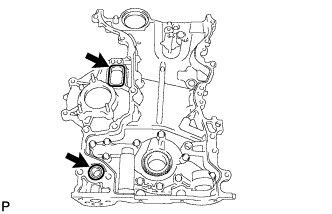
Remove the gasket and O-ring.
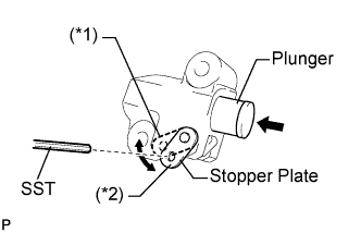
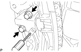
| 15. REMOVE NO. 1 CHAIN TENSIONER ASSEMBLY |
Move the stopper plate upward to release the lock, and push the plunger deep into the tensioner (*1).
Move the stopper plate downward to set the lock, and insert SST into the stopper plate hole (*2).
- SST
- 09240-00020(09242-00250)
Remove the 2 bolts and the No. 1 chain tensioner.
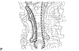
| 16. REMOVE CHAIN TENSIONER SLIPPER |
Remove the chain tensioner slipper.
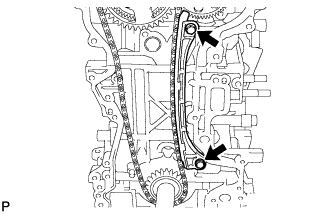
| 17. REMOVE NO. 1 CHAIN VIBRATION DAMPER |
Remove the 2 bolts and vibration damper.
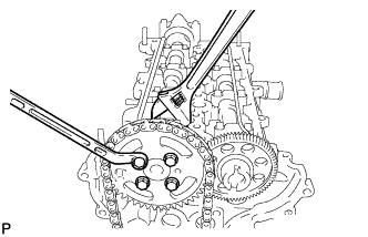
| 18. REMOVE CAMSHAFT TIMING SPROCKET |
Remove the 4 bolts on the sprocket while holding the hexagonal portion of the No. 2 camshaft.
Remove the camshaft timing sprocket, oil pump drive gear, crankshaft timing sprocket and chain.
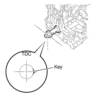
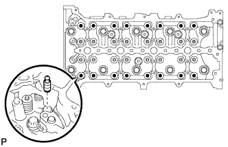
| 19. REMOVE NO. 1 CAMSHAFT |
Check that the following conditions are met:
The No. 1 piston is set to approximately 90° ATDC/compression.
The key is set to the position shown in the illustration.
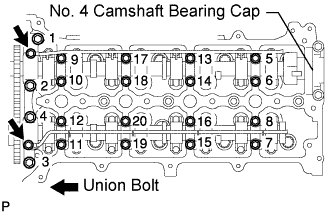
Remove the 2 union bolts.
- ПРИМЕЧАНИЕ:
- Be careful not to deform the camshaft oil delivery pipe LH when loosening the union bolts.
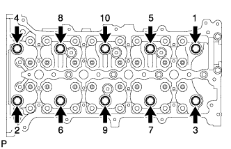
Using several steps, loosen and remove the 20 camshaft bearing cap bolts uniformly in the sequence shown in the illustration.
- ПРИМЕЧАНИЕ:
- Be careful not to deform the oil delivery pipe LH when loosening the bearing cap bolts.
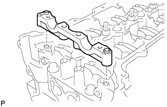
Remove the 8 No. 3 camshaft bearing caps, No. 1 camshaft bearing cap and 2 camshaft oil delivery pipes.
- УКАЗАНИЕ:
- Do not remove the No. 4 bearing cap.
Remove the No. 1 camshaft and No. 2 camshaft.
Remove the No. 2 camshaft bearing cap.
| 20. REMOVE VALVE ROCKER ARM SUB-ASSEMBLY |
Remove the 16 valve rocker arms.
| 21. REMOVE VALVE LASH ADJUSTER ASSEMBLY |
Remove the 16 valve lash adjusters from the cylinder head.
- УКАЗАНИЕ:
- Arrange the removed parts in the correct order.
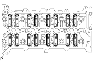
| 22. REMOVE CYLINDER HEAD SUB-ASSEMBLY |
Uniformly loosen the 10 bolts in the sequence shown in the illustration. Remove the 10 cylinder head bolts and plate washers.
- ПРИМЕЧАНИЕ:
- Head warpage or cracking could result from removing the bolts in the incorrect order.
Remove the cylinder head and gasket.
| 23. REMOVE OIL PAN BAFFLE PLATE |
Remove the 4 bolts and baffle plate.
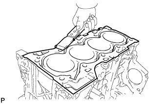
| 24. CLEAN CYLINDER BLOCK SUB-ASSEMBLY |
Using a gasket scraper, remove all the gasket material from the top surface of the cylinder block.
Using a soft brush and solvent, thoroughly clean the cylinder block.