Блок Автоматической Трансмиссии Повторная Сборка. Corolla ZZE150
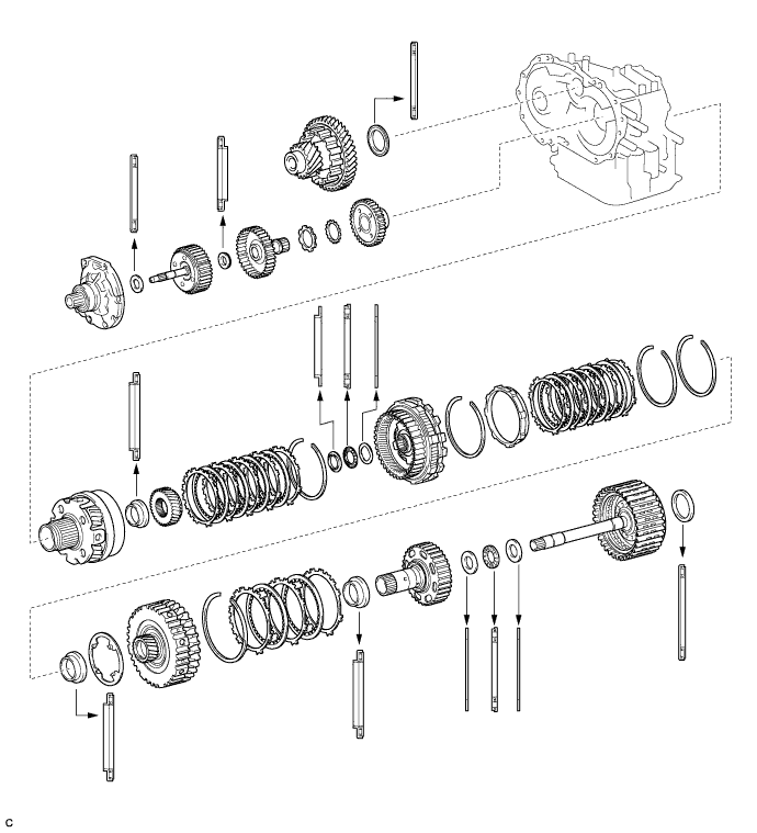
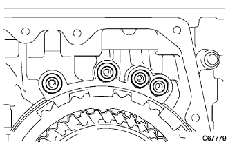
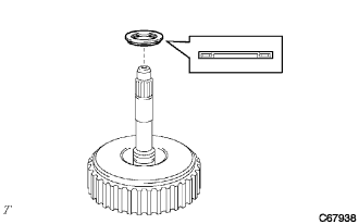
BEARING POSITION
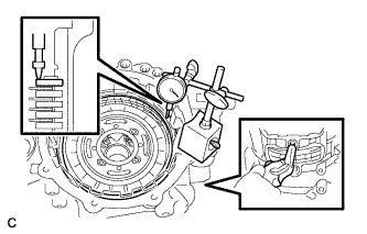
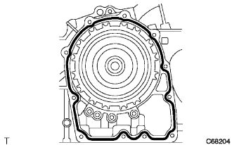
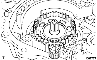
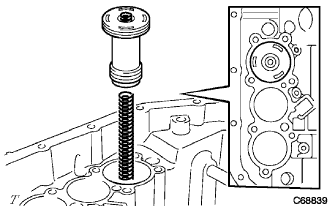
INSPECT DIFFERENTIAL CASE TAPERED ROLLER BEARING PRELOAD
INSTALL TRANSAXLE CASE OIL SEAL
INSTALL FRONT TRANSAXLE CASE OIL SEAL
INSTALL FRONT DRIVE PINION REAR TAPERED ROLLER BEARING
INSTALL FRONT DRIVE PINION FRONT TAPERED ROLLER BEARING
INSTALL DIFFERENTIAL GEAR LUBE APPLY TUBE
INSTALL BEARING LOCK PLATE
INSTALL COUNTER DRIVE GEAR HOLE SNAP RING
INSTALL COUNTER DRIVE GEAR BEARING LH
REMOVE COUNTER DRIVE GEAR BEARING RH
INSTALL MANUAL VALVE LEVER SHAFT OIL SEAL
INSTALL DIFFERENTIAL DRIVE PINION
INSTALL DIFFERENTIAL DRIVE PINION PLUG
INSTALL COUNTER DRIVEN GEAR
INSTALL PARKING LOCK PAWL
INSTALL MANUAL VALVE LEVER SHAFT
INSTALL PARKING LOCK ROD SUB-ASSEMBLY
INSTALL MANUAL VALVE LEVER SUB-ASSEMBLY
INSTALL MANUAL VALVE LEVER SHAFT RETAINER SPRING
INSTALL PARKING LOCK PAWL BRACKET
INSTALL COUNTER DRIVE GEAR
INSTALL PLANETARY GEAR ASSEMBLY
INSTALL COUNTER DRIVE GEAR NUT
INSTALL NO. 2 1ST AND REVERSE BRAKE PISTON O-RING
INSTALL NO. 2 1ST AND REVERSE BRAKE PISTON
INSTALL 1ST AND REVERSE BRAKE RETURN SPRING SUB-ASSEMBLY
INSTALL 1ST AND REVERSE BRAKE DISC
INSPECT PACK CLEARANCE OF FIRST AND REVERSE BRAKE
INSTALL FRONT PLANETARY SUN GEAR
INSTALL OUTER RACE RETAINER
INSTALL NO. 2 ONE-WAY CLUTCH
INSTALL REAR PLANETARY GEAR THRUST NEEDLE ROLLER BEARING
INSTALL REAR PLANETARY GEAR ASSEMBLY
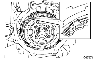
INSPECT NO. 2 ONE-WAY CLUTCH
INSTALL 2ND BRAKE PISTON SLEEVE
INSTALL 2ND BRAKE DISC
INSPECT PACK CLEARANCE OF 2ND BRAKE
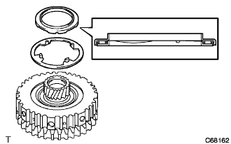
INSTALL 2ND COAST AND OVERDRIVE BRAKE FLANGE HOLE SNAP RING
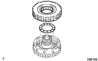
INSTALL ONE-WAY CLUTCH ASSEMBLY
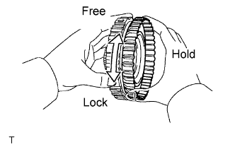
INSPECT ONE-WAY CLUTCH ASSEMBLY
INSTALL REAR PLANETARY SUN GEAR THRUST NEEDLE ROLLER BEARING
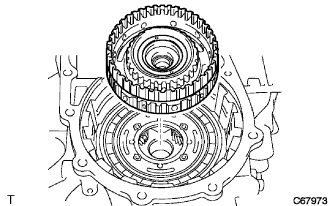
INSTALL REAR PLANETARY SUN GEAR ASSEMBLY
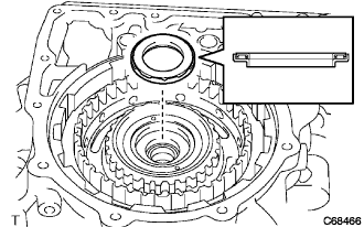
INSTALL REAR NO. 2 PLANETARY SUN GEAR THRUST NEEDLE ROLLER BEARING
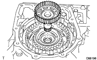
INSTALL DIRECT CLUTCH HUB
INSTALL THRUST NEEDLE ROLLER BEARING
INSTALL 2ND COAST AND OVERDRIVE BRAKE DISC
INSTALL INTERMEDIATE SHAFT ASSEMBLY
INSPECT 2ND COAST AND OVERDRIVE BRAKE CLEARANCE
INSTALL REAR CLUTCH DRUM THRUST NEEDLE ROLLER BEARING
INSPECT INTERMEDIATE SHAFT ASSEMBLY
INSTALL TRANSAXLE CASE GASKET
INSTALL REAR TRANSAXLE COVER ASSEMBLY
INSTALL FORWARD CLUTCH HUB SUB-ASSEMBLY
INSTALL FORWARD CLUTCH HUB THRUST NEEDLE ROLLER BEARING
INSTALL STATOR SHAFT THRUST NEEDLE ROLLER BEARING
INSTALL INPUT SHAFT ASSEMBLY
INSTALL OVERDRIVE BRAKE GASKET
INSTALL DIFFERENTIAL GEAR ASSEMBLY
INSTALL OIL PUMP ASSEMBLY
INSPECT INPUT SHAFT ASSEMBLY
INSPECT INPUT SHAFT END PLAY
INSTALL TRANSAXLE HOUSING
INSTALL C-2 ACCUMULATOR PISTON
INSTALL C-3 ACCUMULATOR PISTON
INSTALL B-2 ACCUMULATOR PISTON
INSTALL CHECK BALL BODY
INSTALL BRAKE DRUM GASKET
INSTALL TRANSAXLE CASE GASKET
INSTALL TRANSAXLE CASE 2ND BRAKE GASKET
INSTALL TRANSMISSION WIRE
INSTALL TRANSMISSION VALVE BODY ASSEMBLY
INSTALL VALVE BODY OIL STRAINER ASSEMBLY
INSTALL AUTOMATIC TRANSAXLE OIL PAN SUB-ASSEMBLY
INSTALL BREATHER PLUG
INSTALL BREATHER PLUG HOSE
INSTALL NO. 1 TRANSAXLE CASE PLUG
INSTALL OIL COOLER TUBE UNION
INSTALL SPEED SENSOR
INSTALL PARK/NEUTRAL POSITION SWITCH ASSEMBLY
INSTALL SPEEDOMETER DRIVEN HOLE COVER SUB-ASSEMBLY
Блок Автоматической Трансмиссии -- Повторная Сборка |
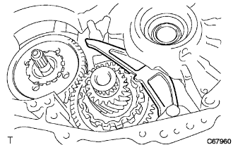
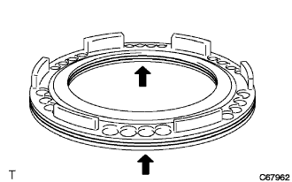
Check bearing position and installation direction.
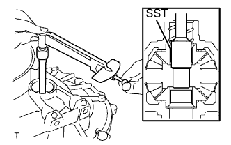
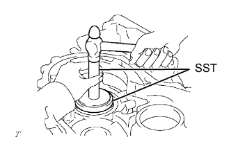
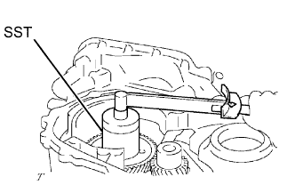
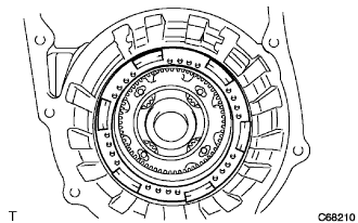
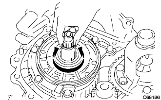
| 2. INSPECT DIFFERENTIAL CASE TAPERED ROLLER BEARING PRELOAD |
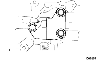
Coat the front differential case and bearing with ATF and install them to the transaxle case.
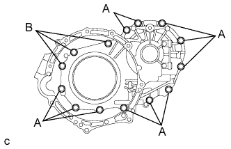
Install the transaxle housing with the 14 bolts.
- Момент затяжки:
- Bolt A:
- 29 Н*м{296 кгс*см, 21 фунт-сила-футов}
- Bolt B:
- 22 Н*м{224 кгс*см, 16 фунт-сила-футов}
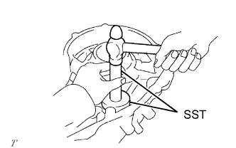
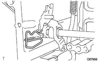
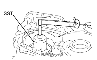
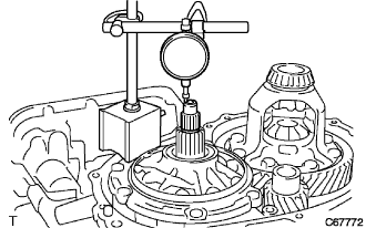
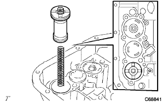
Using SST and a small torque wrench, measure the preload of the differential gear.
- Preload:
Bearing
| Standard
|
New
| 0.98 to 1.57 N*m (10.0 to 16.0 kgf*cm, 8.7 to 13.9 in.*lbf)
|
Used
| 0.49 to 0.78 N*m (5.0 to 8.0 kgf*cm, 4.3 to 6.9 in.*lbf)
|
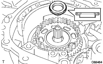
If the preload is not within the specifications, remove the differential from the transaxle case.
Select a new transaxle case side adjusting shim in accordance with the following table.
- Adjusting shim thickness:
Mark
| Thickness mm (in.)
| Mark
| Thickness mm (in.)
|
01
| 1.90 (0.0748)
| 11
| 2.40 (0.0945)
|
02
| 1.95 (0.0768)
| 12
| 2.45 (0.0965)
|
03
| 2.00 (0.0787)
| 13
| 2.50 (0.0984)
|
04
| 2.05 (0.0807)
| 14
| 2.55 (0.1004)
|
05
| 2.10 (0.0827)
| 15
| 2.60 (0.1024)
|
06
| 2.15 (0.0846)
| 16
| 2.65 (0.1043)
|
07
| 2.20 (0.0866)
| 17
| 2.70 (0.1063)
|
08
| 2.25 (0.0885)
| 18
| 2.75 (0.1082)
|
09
| 2.30 (0.0906)
| 19
| 2.80 (0.1102)
|
10
| 2.35 (0.0925)
|
|
|
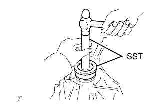
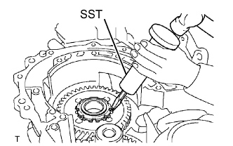
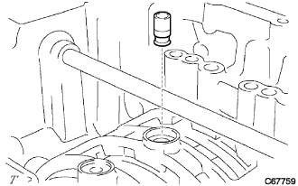
| 3. INSTALL TRANSAXLE CASE OIL SEAL |
Coat the lip of a new oil seal with MP grease.
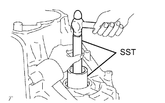
Using SST and a hammer, drive in a new oil seal.
- SST
- 09387-00010
09950-70010(09951-07100)
- Oil seal drive in depth:
- -0.5 to 0.5 mm (-0.020 to 0.020 in.)
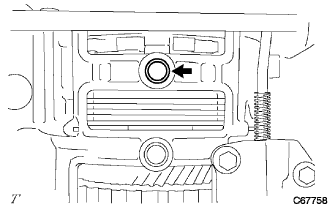
| 4. INSTALL FRONT TRANSAXLE CASE OIL SEAL |
Coat the lip of a new oil seal with MP grease.
Using SST and a hammer, drive in a new oil seal.
- SST
- 09726-27012(09726-02041)
09950-70010(09951-07150)
- Oil seal drive in depth:
- 2.2 to 3.2 mm (0.087 to 0.126 in.)
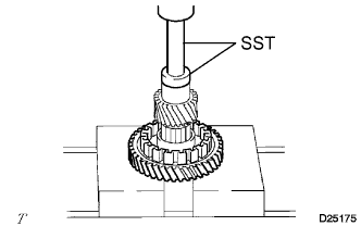
| 5. INSTALL FRONT DRIVE PINION REAR TAPERED ROLLER BEARING |
Install the No. 1 transaxle case plate onto the transaxle case.
Using SST and a hammer, install the front drive pinion rear tapered roller bearing to the transaxle case.
- SST
- 09950-60010(09951-00610)
09950-70010(09951-07150)
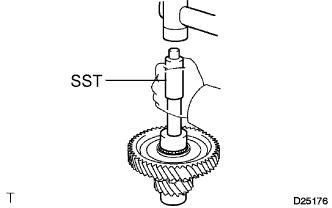
| 6. INSTALL FRONT DRIVE PINION FRONT TAPERED ROLLER BEARING |
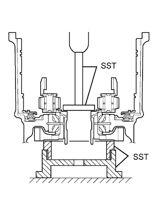
Install the thrust bearing to the transaxle housing.
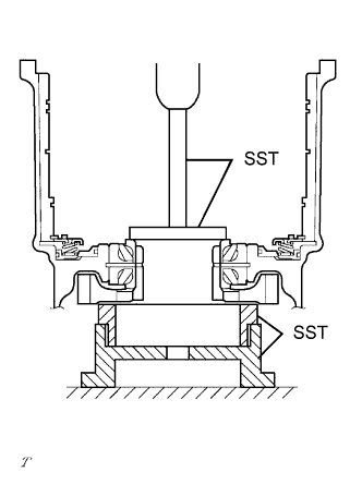
Using SST and a press, install a new front drive pinion front tapered roller bearing to the transaxle housing.
- SST
- 09950-60010(09951-00650)
09950-70010(09951-07150)
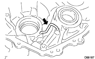
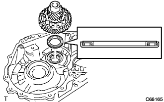
| 7. INSTALL DIFFERENTIAL GEAR LUBE APPLY TUBE |
Install the differential gear lube apply tube to the transaxle housing.
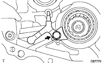
| 8. INSTALL BEARING LOCK PLATE |
Install the bearing lock plate to the transaxle housing with the bolt.
- Момент затяжки:
- 11 Н*м{112 кгс*см, 8 фунт-сила-футов}
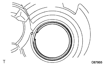
| 9. INSTALL COUNTER DRIVE GEAR HOLE SNAP RING |
Using a screwdriver, install the counter drive gear hole snap ring to the transaxle case.
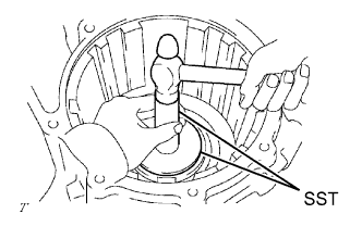
| 10. INSTALL COUNTER DRIVE GEAR BEARING LH |
Using SST and a hammer, install the counter drive gear bearing outer race LH to the transaxle case.
- SST
- 09950-60020(09951-00890)
09950-70010(09951-07150)
Install the counter drive gear bearing LH to the transaxle case.
| 11. REMOVE COUNTER DRIVE GEAR BEARING RH |
Using SST and a hammer, install the counter drive gear bearing outer race RH to the transaxle case.
- SST
- 09950-60020(09951-00890)
09950-70010(09951-07150)
Install the counter drive gear bearing RH to the transaxle case.
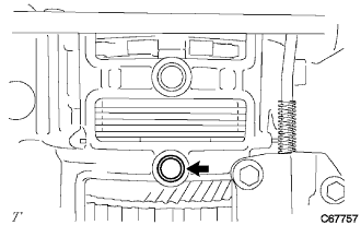
| 12. INSTALL MANUAL VALVE LEVER SHAFT OIL SEAL |
Coat the lip of a new oil seal with MP grease.
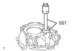
Using SST and a hammer, install a new manual valve lever shaft oil seal.
- SST
- 09950-60010(09951-00220)
09950-70010(09951-07100)
- Oil seal drive in depth:
- -0.5 to 0.5 mm (-0.020 to 0.020 in.)
| 13. INSTALL DIFFERENTIAL DRIVE PINION |
Using SST and a press, install the differential drive pinion to the counter driven gear.
- SST
- 09950-60010(09951-00350)
09950-70010(09951-07150)
- ПРИМЕЧАНИЕ:
- When replacing the counter driven gear, replace the counter drive gear in the transaxle case as well.
- Press in the differential drive pinion until it comes into contact with the counter driven gear.
| 14. INSTALL DIFFERENTIAL DRIVE PINION PLUG |
Using SST and a plastic hammer, install a new differential drive pinion plug to the differential drive pinion.
- SST
- 09221-25026(09221-00071)
- Standard clearance:
- 2.5 to 3.5 mm (0.0984 to 0.1378 in.)
| 15. INSTALL COUNTER DRIVEN GEAR |
Install the counter driven gear and drive pinion thrust bearing to the transaxle case.
| 16. INSTALL PARKING LOCK PAWL |
Coat the parking lock pawl shaft with ATF.
Install the parking lock pawl, parking lock pawl shaft torsion spring and parking lock pawl shaft to the transaxle case.
- ПРИМЕЧАНИЕ:
- Check that the parking lock pawl moves smoothly.
| 17. INSTALL MANUAL VALVE LEVER SHAFT |
Install the manual valve lever shaft to the transaxle case.
- ПРИМЕЧАНИЕ:
- Do not damage the oil seal lip.
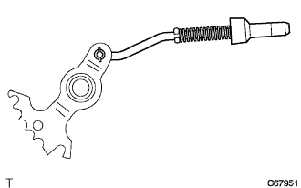
| 18. INSTALL PARKING LOCK ROD SUB-ASSEMBLY |
Install the parking lock rod to the manual valve lever.
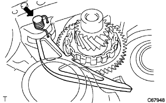
| 19. INSTALL MANUAL VALVE LEVER SUB-ASSEMBLY |
Coat the manual valve lever sub-assembly with ATF.
Install the manual valve lever and a new manual valve lever spacer to the manual valve lever shaft.
Using a pin punch and hammer, drive in the pin.
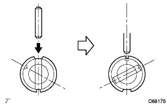
Turn the spacer and lever shaft to align the small hole for locating the staking position mark on the lever shaft.
Using a pin punch, stake the spacer through the small hole.
Check that the spacer does not turn.
| 20. INSTALL MANUAL VALVE LEVER SHAFT RETAINER SPRING |
Install the manual valve lever shaft retainer spring to the manual valve lever shaft.
| 21. INSTALL PARKING LOCK PAWL BRACKET |
Install the parking lock pawl bracket, parking lock rod and cam guide sleeve to the transaxle case with the 3 bolts.
- Момент затяжки:
- 20 Н*м{204 кгс*см, 15 фунт-сила-футов}
| 22. INSTALL COUNTER DRIVE GEAR |
Using SST and a press, install the counter drive gear to the transaxle case.
- SST
- 09223-15030
09527-17011
09950-60010(09951-00650)
09950-70010(09951-07150)
| 23. INSTALL PLANETARY GEAR ASSEMBLY |
Using SST and a press, install the planetary gear assembly to the transaxle case.
- SST
- 09950-60010(09951-00480)
09223-15030
09527-17011
09950-70010(09951-07150)
| 24. INSTALL COUNTER DRIVE GEAR NUT |
Fix the counter driven gear with the parking lock pawl.
Using SST, install a new lock washer and nut.
- SST
- 09387-00120
- Момент затяжки:
- 280 Н*м{2855 кгс*см, 207 фунт-сила-футов}
Using SST and a small torque wrench, measure the rotating torque while turning the counter drive gear at 60 turns per minute.
- SST
- 09387-00120
- Rotating torque:
- 0.20 to 0.49 N*m (2.0 to 5.0 kgf*cm, 1.8 to 4.3 in.*lbf)
Using SST and a hammer, stake the lock nut washer.
- SST
- 09930-00010
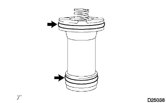
| 25. INSTALL NO. 2 1ST AND REVERSE BRAKE PISTON O-RING |
Coat 2 new O-rings with ATF, and install them to the No. 2 brake piston.
| 26. INSTALL NO. 2 1ST AND REVERSE BRAKE PISTON |
Coat the No. 2 1st and reverse brake piston with ATF, and install it to the transaxle case.
- ПРИМЕЧАНИЕ:
- Do not damage the oil seal lip.
| 27. INSTALL 1ST AND REVERSE BRAKE RETURN SPRING SUB-ASSEMBLY |
Install the 1st and reverse brake return spring sub-assembly to the transaxle case.
Using SST, a press and a screwdriver, install the snap ring.
- SST
- 09387-00070
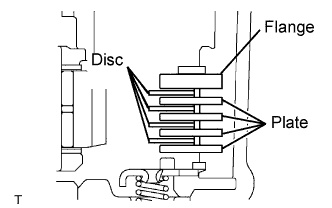
| 28. INSTALL 1ST AND REVERSE BRAKE DISC |
Install the 4 plates, 4 discs and flange to the transaxle case.
Using a screwdriver, install the snap ring.
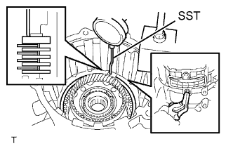
| 29. INSPECT PACK CLEARANCE OF FIRST AND REVERSE BRAKE |
Using SST and a dial indicator, measure the first and reverse brake clearance while pressing the disc and plate from the rear side.
- SST
- 09350-36010(09350-06110)
- Pack clearance:
- 0.806 to 1.206 mm (0.0317 to 0.0475 in.)
- ПРИМЕЧАНИЕ:
- If the clearance is not within the specified range, select a new brake flange.
- УКАЗАНИЕ:
- There are 4 different flange thicknesses.
- Flange thickness:
Mark
| Thickness mm (in.)
| Mark
| Thickness mm (in.)
|
-
| 3.4 (0.134)
| 2
| 3.8 (0.150)
|
1
| 3.6 (0.142)
| 3
| 4.0 (0.157)
|
Check that the 1st and reverse brake piston moves when compressed air is applied (392 kPa, 4.0 kgf/cm2, 57 psi) to the oil hole.
| 30. INSTALL FRONT PLANETARY SUN GEAR |
Install the planetary sun gear and needle roller bearing to the planetary gear assembly.
| 31. INSTALL OUTER RACE RETAINER |
Install the outer retainer to the No. 2 one-way clutch.
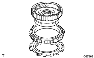
| 32. INSTALL NO. 2 ONE-WAY CLUTCH |
Install the one-way clutch and 2nd brake piston assembly to the rear planetary gear assembly.
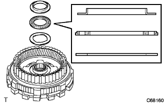
| 33. INSTALL REAR PLANETARY GEAR THRUST NEEDLE ROLLER BEARING |
Install the No. 2 thrust bearing race, the planetary gear thrust needle roller bearing and thrust bearing race to the rear planetary gear assembly.
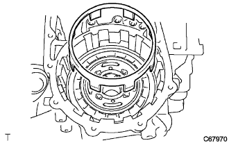
| 34. INSTALL REAR PLANETARY GEAR ASSEMBLY |
Install the rear planetary gear assembly to the transaxle case.
Using a screwdriver, install the snap ring.
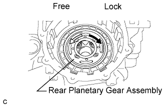
| 35. INSPECT NO. 2 ONE-WAY CLUTCH |
Check that the rear planetary gear assembly turns freely counterclockwise and locks when turned clockwise.
| 36. INSTALL 2ND BRAKE PISTON SLEEVE |
Install the 2nd brake piston sleeve to the transaxle case.
| 37. INSTALL 2ND BRAKE DISC |
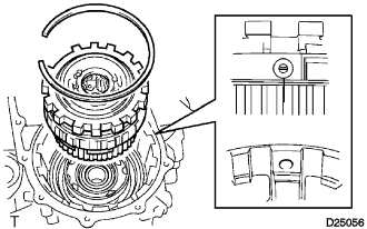
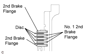
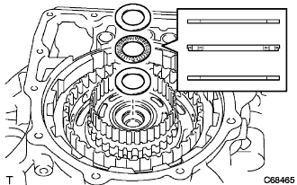
Install the 4 discs, 2 flanges and 3 No. 1 flanges to the transaxle case.
Using a screwdriver, install a snap ring to the transaxle case.
| 38. INSPECT PACK CLEARANCE OF 2ND BRAKE |
Using a dial indicator, measure the 2nd brake pack clearance while applying and releasing compressed air (392 to 785 kPa, 4 to 8 kgf/cm2, 57 to 114 psi).
- Pack clearance:
- 0.847 to 1.247 mm (0.0333 to 0.0491 in.)
- ПРИМЕЧАНИЕ:
- If the clearance is not within the specified range, select a new brake flange.
- УКАЗАНИЕ:
- There are 4 different flange thicknesses.
- Flange thickness:
Mark
| Thickness mm (in.)
| Mark
| Thickness mm (in.)
|
-
| 3.0 (0.118)
| 2
| 3.4 (0.134)
|
1
| 3.2 (0.126)
| 3
| 3.6 (0.142)
|
| 39. INSTALL 2ND COAST AND OVERDRIVE BRAKE FLANGE HOLE SNAP RING |
Using a screwdriver, install a snap ring to the transaxle case.
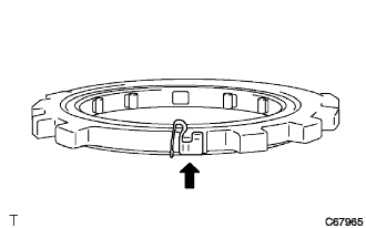
| 40. INSTALL ONE-WAY CLUTCH ASSEMBLY |
Install the No. 2 thrust washer to the rear planetary gear assembly.
Install the one-way clutch assembly to the rear planetary sun gear assembly.
| 41. INSPECT ONE-WAY CLUTCH ASSEMBLY |
Hold the rear planetary sun gear, turn the one-way clutch and check that the one-way clutch turns freely counterclockwise and locks when turned clockwise.
| 42. INSTALL REAR PLANETARY SUN GEAR THRUST NEEDLE ROLLER BEARING |
Install the thrust bearing and a washer to the rear planetary sun gear.
| 43. INSTALL REAR PLANETARY SUN GEAR ASSEMBLY |
Install the rear planetary sun gear assembly.
| 44. INSTALL REAR NO. 2 PLANETARY SUN GEAR THRUST NEEDLE ROLLER BEARING |
Install the thrust bearing to the rear planetary sun gear.
| 45. INSTALL DIRECT CLUTCH HUB |
Install the direct clutch hub.
| 46. INSTALL THRUST NEEDLE ROLLER BEARING |
Install the No. 3 thrust bearing race, the thrust needle roller bearing and the C-2 hub thrust bearing race to the direct clutch hub.
| 47. INSTALL 2ND COAST AND OVERDRIVE BRAKE DISC |
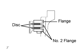
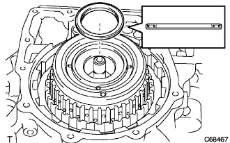
Install the 2 discs, No. 2 flanges and flange to the transaxle case.
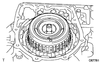
| 48. INSTALL INTERMEDIATE SHAFT ASSEMBLY |
Install the intermediate shaft assembly to the transaxle case.
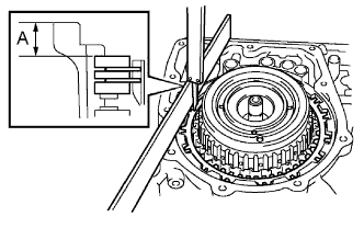
| 49. INSPECT 2ND COAST AND OVERDRIVE BRAKE CLEARANCE |
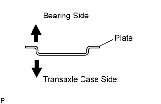
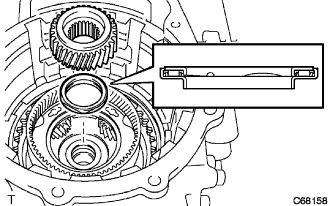
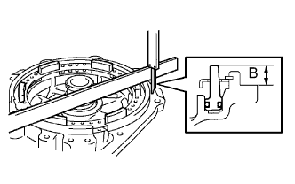
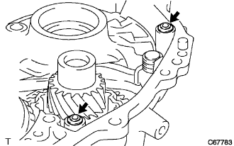
As shown in the illustration, place a straight edge on the transaxle case and measure the distance between the 2nd coast and O/D brake flange and straight edge using vernier calipers. (Dimension A)
As shown in the illustration, place a straight edge on the O/D brake piston and measure the distance between the transaxle rear cover and straight edge using vernier calipers. (Dimension B)
Calculate the piston stroke value using the following formula. Select a flange which meets the piston stroke value and install it.
- Pack clearance:
- 2.091 to 2.491 mm (0.0823 to 0.0981 in.)
- ПРИМЕЧАНИЕ:
- If the clearance is not within the specified range, select a new brake flange.
- УКАЗАНИЕ:
- There are 4 different flange thicknesses.
- Flange thickness:
Mark
| Thickness mm (in.)
| Mark
| Thickness mm (in.)
|
4
| 4.0 (0.1575)
| 6
| 4.4 (0.1732)
|
5
| 4.2 (0.1654)
| 7
| 4.6 (0.1811)
|
| 50. INSTALL REAR CLUTCH DRUM THRUST NEEDLE ROLLER BEARING |
Install the bearing to the intermediate shaft.
| 51. INSPECT INTERMEDIATE SHAFT ASSEMBLY |
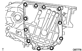
Install the transaxle rear cover with the 11 bolts.
- Момент затяжки:
- 25 Н*м{255 кгс*см, 18 фунт-сила-футов}
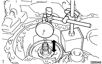
Using a dial indicator, measure the intermediate shaft end play.
- Standard clearance:
- 0.204 to 0.966 mm (0.008 to 0.038 in.)
If the end play is not as specified, select and replace the rear clutch drum thrust needle roller bearing.
- УКАЗАНИЕ:
- There are 2 different trust needle roller bearing thicknesses.
Color
| Thickness mm (in.)
|
Brown
| 2.5 (0.0984)
|
Black
| 2.8 (0.1102)
|
Remove the 11 bolts and the transaxle rear cover.
| 52. INSTALL TRANSAXLE CASE GASKET |
Install 4 new gaskets to the transaxle case.
| 53. INSTALL REAR TRANSAXLE COVER ASSEMBLY |
Apply seal packing to the transaxle case.
- Seal packing:
- Toyota Genuine Seal Packing 1281, Three Bond 1281 or equivalent
Install the rear transaxle cover with the 11 bolts.
- Момент затяжки:
- 25 Н*м{255 кгс*см, 18 фунт-сила-футов}
| 54. INSTALL FORWARD CLUTCH HUB SUB-ASSEMBLY |
Install the forward clutch hub sub-assembly onto the transaxle case.
| 55. INSTALL FORWARD CLUTCH HUB THRUST NEEDLE ROLLER BEARING |
Install the bearing to the forward clutch hub.
| 56. INSTALL STATOR SHAFT THRUST NEEDLE ROLLER BEARING |
Install the bearing to the input shaft assembly.
| 57. INSTALL INPUT SHAFT ASSEMBLY |
Install the input shaft assembly to the transaxle case.
| 58. INSTALL OVERDRIVE BRAKE GASKET |
Install 2 new gaskets to the transaxle case.
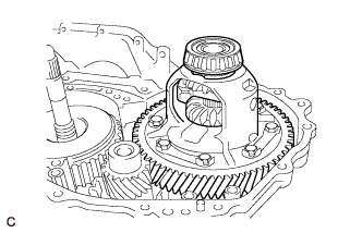
| 59. INSTALL DIFFERENTIAL GEAR ASSEMBLY |
Install the differential gear assembly to the transaxle case.
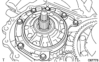
| 60. INSTALL OIL PUMP ASSEMBLY |
Install the oil pump with the 7 bolts.
- Момент затяжки:
- 22 Н*м{224 кгс*см, 16 фунт-сила-футов}
| 61. INSPECT INPUT SHAFT ASSEMBLY |
Make sure that the input shaft turns smoothly.
| 62. INSPECT INPUT SHAFT END PLAY |
Measure the end play in the axial direction.
- End play:
- 0.374 to 1.292 mm (0.0147 to 0.0509 in.)
If the end play is not as specified, replace the forward clutch hub thrust needle roller bearing and the stator shaft thrust needle bearing.
| 63. INSTALL TRANSAXLE HOUSING |
Apply seal packing to the transaxle case.
- Seal packing:
- Toyota Genuine Seal Packing 1281, Three Bond 1281 or equivalent
Install the transaxle housing with the 14 bolts.
- Момент затяжки:
- Bolt A:
- 29 Н*м{296 кгс*см, 21 фунт-сила-футов}
- Bolt B:
- 22 Н*м{224 кгс*см, 16 фунт-сила-футов}
| 64. INSTALL C-2 ACCUMULATOR PISTON |
Coat 2 new O-rings with ATF and install them to the C-2 accumulator piston.
- ПРИМЕЧАНИЕ:
- Do not damage the O-rings.
Install the spring and C-2 accumulator piston.
- Accumulator spring:
Spring
| Free length/
Outer diameter mm (in.)
| Color
|
C-2
| 66.90 (2.6339)
17.20 (0.6772)
| -
|
| 65. INSTALL C-3 ACCUMULATOR PISTON |
Coat 2 new O-rings with ATF and install them to the C-3 accumulator piston.
- ПРИМЕЧАНИЕ:
- Do not damage the O-rings.
Install the spring and C-3 accumulator piston.
- Accumulator spring:
Spring
| Free length/
Outer diameter mm (in.)
| Color
|
C-3
| 87.30 (3.4370)
18.70 (0.7362)
| Orange
|
| 66. INSTALL B-2 ACCUMULATOR PISTON |
Coat 2 new O-rings with ATF and install them to the B-2 accumulator piston.
- ПРИМЕЧАНИЕ:
- Do not damage the O-rings.
Install the spring and B-2 accumulator piston.
- Accumulator spring:
Spring
| Free length/
Outer diameter mm (in.)
| Color
|
B-2
| 66.90 (2.6339)
15.50 (0.6102)
| White
|
| 67. INSTALL CHECK BALL BODY |
Install the spring and check ball body.
| 68. INSTALL BRAKE DRUM GASKET |
Install a new brake drum gasket.
| 69. INSTALL TRANSAXLE CASE GASKET |
Coat a new transaxle case gasket with ATF, and install it to the transaxle case.
| 70. INSTALL TRANSAXLE CASE 2ND BRAKE GASKET |
Coat a new transaxle case 2nd brake gasket with ATF, and install it to the transaxle case.
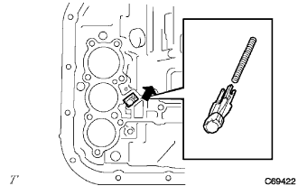
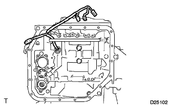
| 71. INSTALL TRANSMISSION WIRE |
Coat a new O-ring with ATF, and install it to the transmission wire.
Insert the transmission wire to the transaxle.
Install the transmission wire with the bolt.
- Момент затяжки:
- 5.4 Н*м{55 кгс*см, 48 фунт-сила-дюймов}
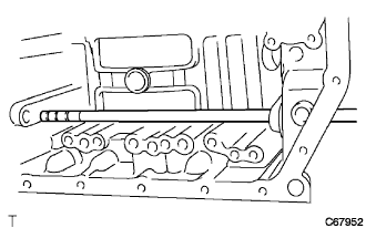
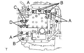
| 72. INSTALL TRANSMISSION VALVE BODY ASSEMBLY |
Align the groove of the manual valve with the pin of the manual valve lever.
Temporarily install the valve body with the 13 bolts.
- Bolt length:
- Bolt A: 32 mm (1.26 in.)
Bolt B: 22 mm (0.87 in.)
Bolt C: 55 mm (2.17 in.)
Bolt D: 45 mm (1.77 in.)
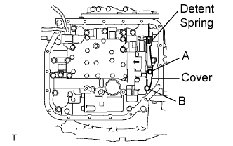
Temporarily install the detent spring and detent spring cover with the 2 bolts.
- Bolt length:
- Bolt A: 14 mm (0.55 in.)
Bolt B: 45 mm (1.77 in.)
Check that the manual valve lever is in contact with the center of the roller at the tip of the detent spring.
Tighten the 15 bolts.
- Момент затяжки:
- 11 Н*м{112 кгс*см, 8 фунт-сила-футов}
Connect the 5 solenoid connectors.
Install the ATF temperature sensor with the lock plate and bolt.
- Момент затяжки:
- 11 Н*м{112 кгс*см, 8 фунт-сила-футов}
- Bolt length:
- 55 mm (2.17 in.)
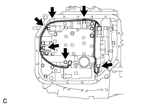
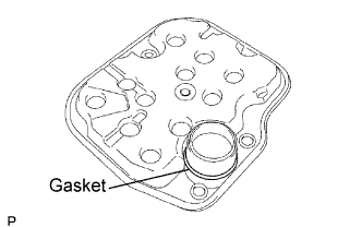
| 73. INSTALL VALVE BODY OIL STRAINER ASSEMBLY |
Coat a new O-ring with ATF, and install it to the oil strainer.
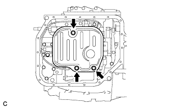
Install the valve body oil strainer assembly to the automatic transaxle with the 3 bolts.
- Момент затяжки:
- 11 Н*м{112 кгс*см, 8 фунт-сила-футов}
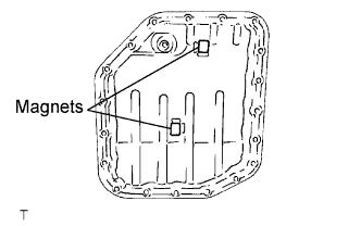
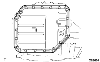
| 74. INSTALL AUTOMATIC TRANSAXLE OIL PAN SUB-ASSEMBLY |
Install the 2 magnets to the oil pan.
Install a new oil pan gasket to the oil pan.
Install the oil pan with the 19 bolts.
- Момент затяжки:
- 7.8 Н*м{80 кгс*см, 69 фунт-сила-дюймов}
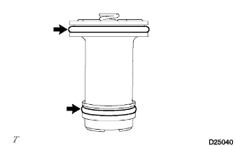
| 75. INSTALL BREATHER PLUG |
Install the breather plug to the transaxle case.
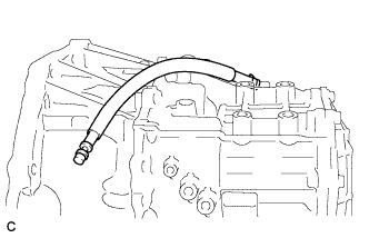
| 76. INSTALL BREATHER PLUG HOSE |
Install the breather plug hose to the breather plug.
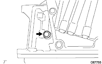
| 77. INSTALL NO. 1 TRANSAXLE CASE PLUG |
Coat 5 new O-rings with ATF, and install them to the No. 1 transaxle case plugs.
Install the 4 No. 1 transaxle case plugs to the transaxle housing and transaxle case.
- Момент затяжки:
- 7.4 Н*м{76 кгс*см, 66 фунт-сила-дюймов}
Install the No. 1 transaxle case plug to the transaxle case.
- Момент затяжки:
- 7.4 Н*м{76 кгс*см, 66 фунт-сила-дюймов}
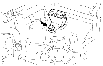
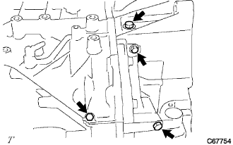
| 78. INSTALL OIL COOLER TUBE UNION |
Coat 2 new O-rings with ATF, and install them into the 2 oil cooler tube unions.
Install the 2 oil cooler tube unions to the transaxle case.
- Момент затяжки:
- 27 Н*м{275 кгс*см, 20 фунт-сила-футов}
Coat a new O-ring with ATF, and install it to the speed sensor.
Install the speed sensor to the transaxle case with the bolt.
- Момент затяжки:
- 5.4 Н*м{55 кгс*см, 48 фунт-сила-дюймов}
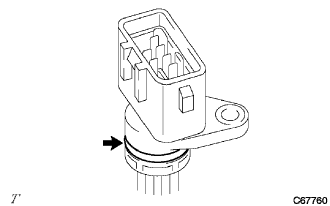
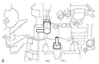
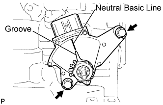
| 80. INSTALL PARK/NEUTRAL POSITION SWITCH ASSEMBLY |
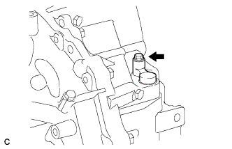
Install the park/neutral position switch assembly to the automatic transaxle.
Temporarily install the 2 bolts.
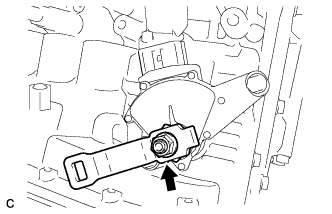
Replace the lock plate with a new one and tighten the manual valve shaft nut.
- Момент затяжки:
- 6.9 Н*м{70 кгс*см, 61 фунт-сила-дюймов}
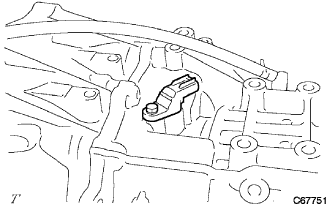
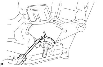
Temporarily install the control shaft lever.
Turn the lever counterclockwise until it stops, then turn it clockwise 2 notches.
Remove the control shaft lever.
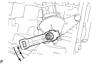
Align the groove with the neutral basic line.
Hold the switch in this position and tighten the 2 bolts.
- Момент затяжки:
- 5.4 Н*м{55 кгс*см, 48 фунт-сила-дюймов}
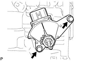
Using a screwdriver, stake the nut with the lock plate.
Install the control shaft lever with the nut and washer.
- Момент затяжки:
- 13 Н*м{133 кгс*см, 10 фунт-сила-футов}
| 81. INSTALL SPEEDOMETER DRIVEN HOLE COVER SUB-ASSEMBLY |
Coat a new O-ring with ATF and install it to the speedometer driven hole cover sub-assembly.
Install the speedometer driven hole cover sub-assembly to the transaxle housing.
- Момент затяжки:
- 7.0 Н*м{71 кгс*см, 62 фунт-сила-дюймов}