INSTALL DRIVE PLATE AND TORQUE CONVERTER CLUTCH SETTING BOLT
INSTALL COMPRESSOR WITH PULLEY ASSEMBLY (w/ Air Conditioning System)
Автоматическая Трансмиссия В Блоке С Главной Передачей -- Установка |
| 1. INSPECT TORQUE CONVERTER CLUTCH ASSEMBLY |
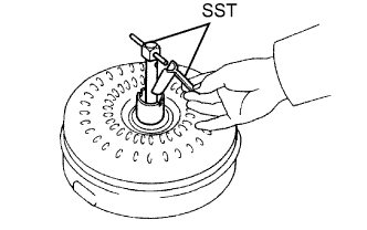
Inspect the one-way clutch.
Set SST so that it fits into the notch of the converter hub and the notch of the outer race of the one-way clutch.
- SST
- 09350-32014(09351-32010,09351-32020)
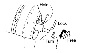
Stand the torque converter up and turn the SST.
Check that it rotates smoothly when turned clockwise and locks up when turned counterclockwise.- SST
- 09350-32014(09351-32010,09351-32020)
Replace the converter if the one-way clutch still does not operate as specified.
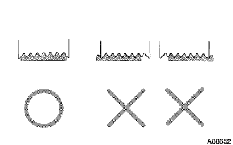
Determine the condition of the torque converter clutch assembly.
Check that the following conditions are met:
- During the stall test or when the shift lever is in the N position, metallic sounds are not emitted from the torque converter clutch.
- The one-way clutch turns in one direction and locks in the other direction.
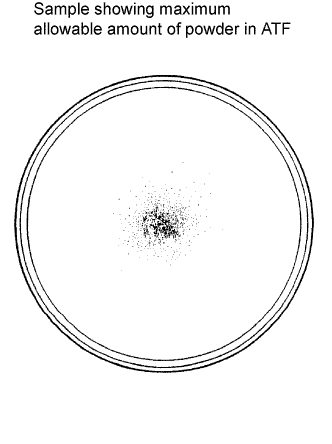
- The amount of powder in the ATF is not greater than the sample shown in the illustration.
- УКАЗАНИЕ:
- The sample illustration shows approximately 0.25 liters (0.26 US qts, 0.22 Imp. qts) of the ATF taken from a removed torque converter clutch.
- During the stall test or when the shift lever is in the N position, metallic sounds are not emitted from the torque converter clutch.
 |
Replace the ATF in the torque converter clutch.
If the ATF is discolored and/or has a foul odor, rock the torque converter to move the fluid around inside it. Drain the ATF with the mounting surface of the converter facing upward.
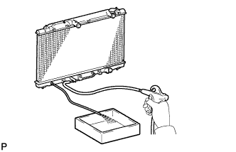
Clean and check the oil cooler and oil pipe line.
If the torque converter clutch is inspected or the ATF is changed, clean the oil cooler and oil pipe line.
- УКАЗАНИЕ:
- Spray compressed air of 196 kPa (2 kgf/cm2, 28 psi) from the inlet hose.
- If excessive fine powder is found in the ATF, add new ATF using a bucket pump and clean it again.
If the ATF is cloudy, inspect the oil cooler (radiator).
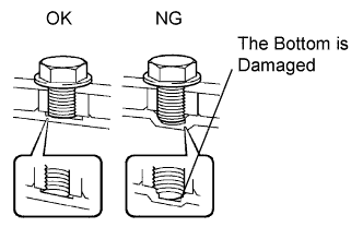
Prevent deformation of the torque converter clutch and damage to the oil pump gear.
When any marks due to interference are found on the end of the bolt for the torque converter clutch and on the bottom of the bolt hole, replace the bolt and the torque converter clutch.
All of the bolts must be the same length.
The bolts with washers must be used.
 |
| 2. INSTALL TORQUE CONVERTER CLUTCH ASSEMBLY |
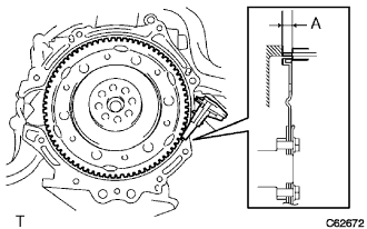
Using vernier calipers, measure dimension A between the transaxle fitting part of the engine and the converter fitting part of the drive plate.
 |
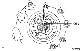
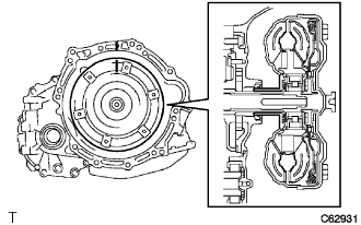
Set the key at the top of the front oil pump drive gear and put a mark on the housing.
 |
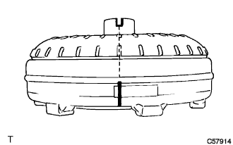
Put a mark on the torque converter so that its groove is clearly indicated.
 |
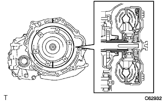
Align the mark on the case with the one on the converter and fit the spline of the input shaft to the spline of the turbine runner.
 |
Rotating the converter, fit the spline of the stator shaft with that of the stator.
- УКАЗАНИЕ:
- Rotate it approximately 180 degrees.
 |
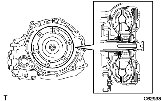
Rotating the converter, align the mark on the case with the one on the converter again and fit the key of the oil pump drive gear into the keyway of the converter.
- ПРИМЕЧАНИЕ:
- Do not push the converter excessively when rotating it.
 |
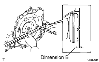
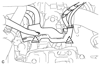
Using vernier calipers and a straight edge, measure dimension B shown in the illustration and check that dimension B is greater than dimension A, which was measured in step (a).
- Standard:
- A + 1 mm (0.04 in.) or more
- ПРИМЕЧАНИЕ:
- Subtract the thickness of the straight edge from the measured value to gain dimension B.
 |
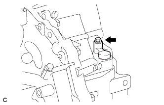
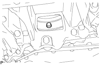
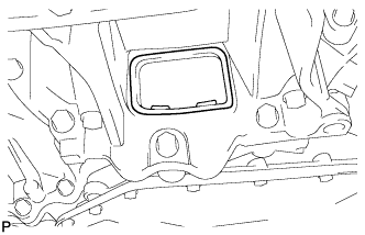
| 3. INSTALL SPEEDOMETER DRIVEN HOLE COVER SUB-ASSEMBLY |
Install the speedometer driven hole cover sub-assembly to the automatic transaxle with the bolt.
- Момент затяжки:
- 7.0 Н*м{71 кгс*см, 62 фунт-сила-дюймов}
 |
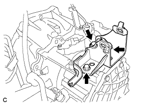
| 4. INSTALL NO. 1 TRANSMISSION CONTROL CABLE BRACKET |
Install the No. 1 transmission control cable bracket to the automatic transaxle with the 2 bolts.
- Момент затяжки:
- 12 Н*м{122 кгс*см, 9 фунт-сила-футов}
 |
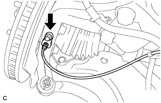
Connect the 2 connectors and install the clamp to the automatic transaxle.
| 5. INSTALL OIL LEVEL GAUGE GUIDE |
Apply ATF to a new O-ring, and install it to the oil level gauge guide.
Install the oil level gauge guide to the automatic transaxle with the bolt.
- Момент затяжки:
- 12 Н*м{122 кгс*см, 9 фунт-сила-футов}
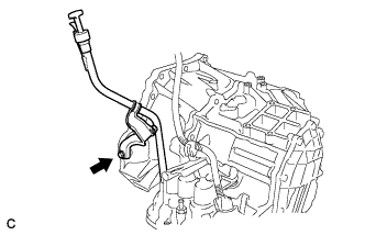 |
Install the oil level gauge sub-assembly to the oil level gauge guide.
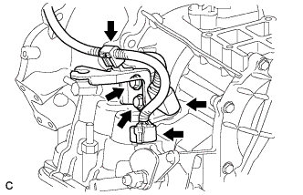
| 6. INSTALL OIL COOLER TUBE SUB-ASSEMBLY |
Connect the 2 oil cooler hoses to the 2 unions with the 2 hose clamps.
 |
Install the oil cooler tube sub-assembly to the automatic transaxle with the bolt.
- Момент затяжки:
- 5.5 Н*м{56 кгс*см, 49 фунт-сила-дюймов}
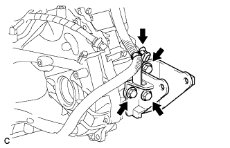
| 7. INSTALL TRANSMISSION CONTROL CABLE SUPPORT |
Install the transmission control cable support to the automatic transaxle with the bolt.
- Момент затяжки:
- 5.0 Н*м{51 кгс*см, 44 фунт-сила-дюймов}
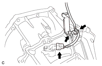 |
Connect the clamp onto the transmission control cable support and connect the speed sensor connector to the speed sensor.
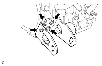
| 8. INSTALL ENGINE MOUNTING REAR BRACKET |
Install the engine mounting rear bracket to the automatic transaxle with the 3 bolts.
- Момент затяжки:
- 45 Н*м{459 кгс*см, 33 фунт-сила-футов}
 |
Install the wire harness to the engine mounting rear bracket with the wire harness clamp.
| 9. INSTALL ENGINE MOUNTING FRONT BRACKET |
Install the engine mounting front bracket to the automatic transaxle with the 4 bolts.
- Момент затяжки:
- 64 Н*м{653 кгс*см, 47 фунт-сила-футов}
 |
| 10. INSTALL ENGINE MOUNTING BRACKET LH |
Install the engine mounting bracket LH to the automatic transaxle with the 3 bolts.
- Момент затяжки:
- 64 Н*м{653 кгс*см, 47 фунт-сила-футов}
 |
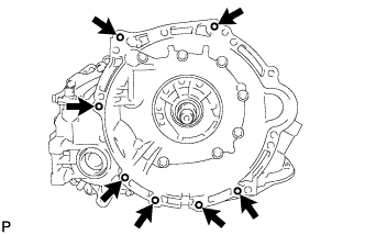
| 11. INSTALL AUTOMATIC TRANSAXLE ASSEMBLY |
Install the automatic transaxle to the engine with the 7 bolts.
- Момент затяжки:
- 29 Н*м{296 кгс*см, 21 фунт-сила-футов}
 |
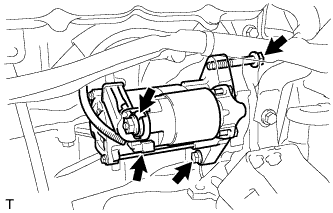
| 12. INSTALL STARTER ASSEMBLY |
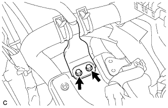
Install the starter assembly with the 2 bolts.
- Момент затяжки:
- 37 Н*м{377 кгс*см, 27 фунт-сила-футов}
 |
Connect the connector.
Connect terminal 30 with the nut.
- Момент затяжки:
- 9.8 Н*м{100 кгс*см, 87 фунт-сила-дюймов}
Close the terminal cap.
Install the wire harness bracket with the bolt.
- Момент затяжки:
- 8.4 Н*м{85 кгс*см, 74 фунт-сила-дюймов}
 |
Install the 2 harness clamps.
| 13. INSTALL FLYWHEEL HOUSING SIDE COVER |
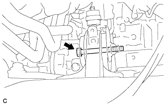
| 14. INSTALL REAR ENGINE MOUNTING INSULATOR |
Install the rear engine mounting insulator to the engine mounting bracket with the through bolt.
- Момент затяжки:
- 95 Н*м{969 кгс*см, 70 фунт-сила-футов}
 |
| 15. INSTALL ENGINE ASSEMBLY WITH TRANSAXLE |
Set the engine assembly with transaxle and front suspension crossmember on the engine lifter.
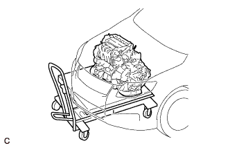 |
Operate the engine lifter and lift the engine assembly with transaxle and front suspension crossmember to the position where the engine mounting insulator RH and LH can be installed.
- ПРЕДОСТЕРЕЖЕНИЕ:
- Do not raise the engine more than necessary. If the engine is raised excessively, the vehicle may also be lifted up.
- ПРИМЕЧАНИЕ:
- Make sure that the engine is clear of all wiring and hoses.
- While raising the engine into the vehicle, do not allow it to contact the vehicle.
Install the engine mounting insulator LH with the through bolt and nut.
- Момент затяжки:
- 56 Н*м{571 кгс*см, 41 фунт-сила-футов}
 |
Install the engine mounting insulator RH with the bolt and 2 nuts.
- Момент затяжки:
- Nut A:
- 95 Н*м{969 кгс*см, 70 фунт-сила-футов}
- Nut B:
- 52 Н*м{530 кгс*см, 38 фунт-сила-футов}
- Bolt:
- 95 Н*м{969 кгс*см, 70 фунт-сила-футов}
 |
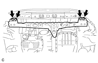
| 16. INSTALL FRONT CROSSMEMBER |
Install the front crossmember with the 4 bolts.
- Момент затяжки:
- 96 Н*м{979 кгс*см, 71 фунт-сила-футов}
 |
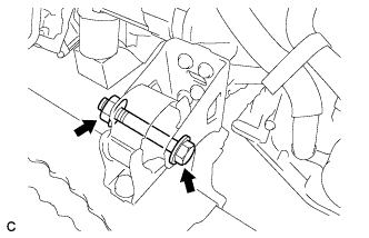
Install the engine mounting insulator front to the engine mounting bracket front with the bolt and nut.
- Момент затяжки:
- 145 Н*м{1479 кгс*см, 107 фунт-сила-футов}
 |
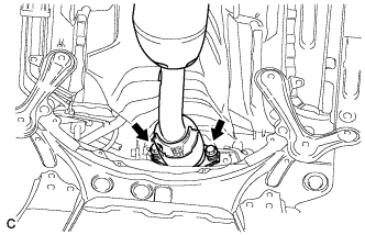
| 17. INSTALL FRONT SUSPENSION CROSSMEMBER SUB-ASSEMBLY |
Подоприте поперечину передней подвески телескопическим гидравлическим домкратом.
Поочередно вставляя SST в контрольные отверстия на правом и левом подрамниках передней подвески, в несколько приемов затяните 2 болта A, 2 болта B и 2 гайки с правой и левой сторон с номинальным моментом затяжки.
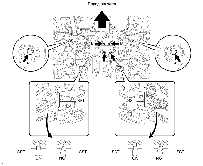
- SST
- 09670-00020
- Момент затяжки:
- Болт A:
- 145 Н*м{1479 кгс*см, 107 фунт-сила-футов}
- Болт B:
- 95 Н*м{969 кгс*см, 70 фунт-сила-футов}
- Гайка:
- 93 Н*м{948 кгс*см, 69 фунт-сила-футов}
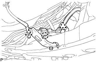
Введите в зацепление 2 зажима и захват, и установите жгут проводов кислородного датчика на подрамник передней подвески в сборе.
 |
| 18. INSTALL FRONT SUSPENSION MEMBER REAR BRACE LH |
Установите левую заднюю скобу элемента передней подвески и закрепите ее 3 болтами.
- Момент затяжки:
- Болт A:
- 145 Н*м{1479 кгс*см, 107 фунт-сила-футов}
- Болт B :
- 93 Н*м{948 кгс*см, 69 фунт-сила-футов}
 |
| 19. INSTALL FRONT SUSPENSION MEMBER REAR BRACE RH |
- УКАЗАНИЕ:
- Perform the same procedure for the LH side.
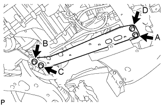
| 20. INSTALL FRONT SUSPENSION MEMBER REINFORCEMENT LH |
Установите левое усиление элемента передней подвески и закрепите его 4 болтами.
- Момент затяжки:
- 96 Н*м{979 кгс*см, 71 фунт-сила-футов}
- ПРИМЕЧАНИЕ:
- Предварительно затяните болты A и B, а затем полностью затяните 4 болта в следующем порядке: C, B, D и A.
 |
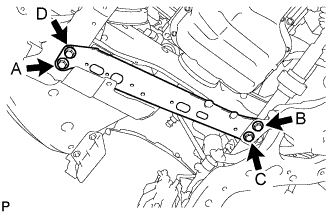
| 21. INSTALL FRONT SUSPENSION MEMBER REINFORCEMENT RH |
Установите правое усиление элемента передней подвески и закрепите его 4 болтами.
- Момент затяжки:
- 96 Н*м{979 кгс*см, 71 фунт-сила-футов}
- ПРИМЕЧАНИЕ:
- Предварительно затяните болты A и B, а затем полностью затяните 4 болта в следующем порядке: C, B, D и A.
 |
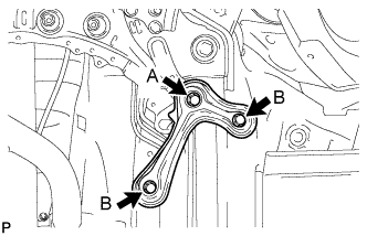
| 22. INSTALL ENGINE FRONT MOUNTING BRACKET REINFORCEMENT LOWER |
Установите нижнее усиление переднего кронштейна опоры двигателя и закрепите его 2 болтами.
- Момент затяжки:
- 96 Н*м{979 кгс*см, 71 фунт-сила-футов}
 |
| 23. INSTALL DRIVE PLATE AND TORQUE CONVERTER CLUTCH SETTING BOLT |
Apply a few drops of adhesive to 2 threads on the tip of the 6 torque converter clutch mounting bolts.
- Adhesive:
- Toyota Genuine Adhesive 1324, Three Bond 1324 or equivalent
Install the 6 torque converter set bolts while holding the crankshaft pulley bolt with a wrench.
- Момент затяжки:
- 28 Н*м{286 кгс*см, 21 фунт-сила-футов}
- ПРИМЕЧАНИЕ:
- First install the black colored bolt, and then install the remaining 5 bolts.
 |
| 24. INSTALL FLYWHEEL HOUSING UNDER COVER |
Install the flywheel housing under cover to the automatic transaxle.
 |
| 25. INSTALL FRONT DRIVE SHAFT ASSEMBLY LH |
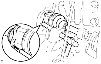 |
Смажьте шлицевую часть вала внутреннего шарнира трансмиссионным маслом.
Совместите шлицы валов и вбейте приводной вал с помощью латунного стержня и молотка.
- ПРИМЕЧАНИЕ:
- Установите пружинное стопорное кольцо так, чтобы разрез был направлен вниз.
- Будьте осторожны, чтобы не повредить сальник, чехол и пыльник.
| 26. INSTALL FRONT DRIVE SHAFT ASSEMBLY RH |
- УКАЗАНИЕ:
- Use the same procedures described for the LH side.
| 27. INSTALL STEERING KNUCKLE WITH AXLE HUB LH |
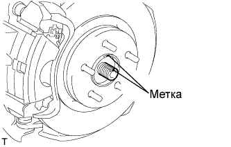 |
Совместите метки и подсоедините передний приводной вал в сборе к левой передней полуоси в сборе.
| 28. INSTALL STEERING KNUCKLE WITH AXLE HUB RH |
- УКАЗАНИЕ:
- Use the same procedures described for the LH side.
| 29. INSTALL FRONT SUSPENSION ARM SUB-ASSEMBLY LOWER NO. 1 LH |
Подсоедините нижний рычаг передней подвески к переднему нижнему шаровому шарниру и закрепите болтом и 2 гайками.
- Момент затяжки:
- 89 Н*м{908 кгс*см, 66 фунт-сила-футов}
 |
| 30. INSTALL FRONT SUSPENSION ARM SUB-ASSEMBLY LOWER NO. 1 RH |
- УКАЗАНИЕ:
- Use the same procedures described for the LH side.
| 31. INSTALL FRONT STABILIZER LINK ASSEMBLY LH |
Установите стойку переднего стабилизатора в сборе на передний амортизатор с цилиндрической винтовой пружиной, закрепив ее гайкой.
- Момент затяжки:
- 74 Н*м{755 кгс*см, 55 фунт-сила-футов}
- ПРИМЕЧАНИЕ:
- Если шаровой шарнир поворачивается вместе с гайкой, зафиксируйте болт пальца с помощью шестигранного ключа (на 6 мм).
 |
| 32. INSTALL FRONT STABILIZER LINK ASSEMBLY RH |
- УКАЗАНИЕ:
- Use the same procedures described for the LH side.
| 33. CONNECT TIE ROD END SUB-ASSEMBLY LH |
Подсоедините наконечник левой рулевой тяги в сборе к поворотному кулаку и закрепите его гайкой.
- Момент затяжки:
- 49 Н*м{500 кгс*см, 36 фунт-сила-футов}
- ПРИМЕЧАНИЕ:
- Если отверстия под шплинт не совпадают, дополнительно затяните гайку (до 60°).
 |
Установите новый шплинт.
| 34. CONNECT TIE ROD END SUB-ASSEMBLY RH |
- УКАЗАНИЕ:
- Use the same procedures described for the LH side.
| 35. INSTALL FRONT SPEED SENSOR LH |
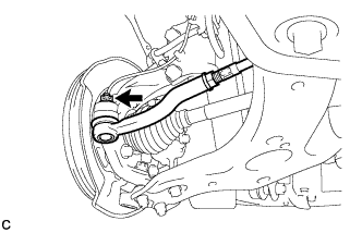
Установите передний датчик частоты вращения и передний гибкий шланг на передний амортизатор, закрепив их болтом и зажимом.
- Момент затяжки:
- 29 Н*м{296 кгс*см, 21 фунт-сила-футов}
- ПРИМЕЧАНИЕ:
- Не допускайте перекручивания переднего датчика частоты вращения при установке.
- УКАЗАНИЕ:
- Сначала установите передний гибкий шланг, а затем кронштейн жгута проводов датчика частоты вращения.
 |
Установите передний датчик частоты вращения на поворотный кулак и закрепите его болтом.
- Момент затяжки:
- 8,5 Н*м{87 кгс*см, 76 фунт-сила-дюймов}
- ПРИМЕЧАНИЕ:
- Не допускайте перекручивания переднего датчика частоты вращения при установке.
 |
| 36. INSTALL FRONT SPEED SENSOR RH |
- УКАЗАНИЕ:
- Use the same procedures described for the LH side.
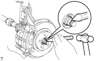
| 37. INSTALL FRONT AXLE HUB LH NUT |
С помощью молотка и зубила накерните гайку ступицы переднего колеса.
 |
| 38. INSTALL FRONT AXLE HUB RH NUT |
- УКАЗАНИЕ:
- Use the same procedures described for the LH side.
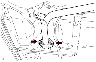
| 39. INSTALL FRONT EXHAUST PIPE ASSEMBLY |
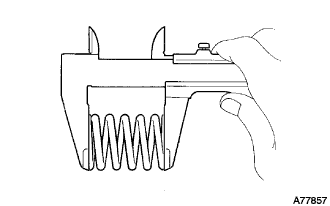
Using vernier calipers, measure the free length of the compression springs.
Minimum (front) 41.5 mm (1.63 in.) Minimum (rear) 38.5 mm (1.52 in.) - УКАЗАНИЕ:
- If the free length is less than the minimum, replace the compression spring.
 |
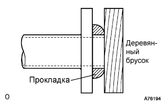
Using a plastic hammer and wooden block, tap in a new gasket until its surface is flush with the exhaust manifold.
- ПРИМЕЧАНИЕ:
- Be careful with the installation direction of the gasket.
- Do not reuse the gasket.
- Do not damage the gasket.
- Do not push in the gasket by using the exhaust pipe when connecting it.
 |
Install the exhaust pipe support, and then install the front exhaust pipe assembly with the 2 compression springs and 2 bolts.
- Момент затяжки:
- 43 Н*м{439 кгс*см, 32 фунт-сила-футов}
 |
Using a plastic hammer and wooden block, tap in a new gasket until its surface is flush with the front exhaust pipe assembly.
- ПРИМЕЧАНИЕ:
- Be careful with the installation direction of the gasket.
- Do not reuse the gasket.
- Do not damage the gasket.
- Do not push in the gasket by using the exhaust pipe when connecting it.
|
Connect the front exhaust pipe assembly to the center exhaust pipe assembly with the 2 compression springs and 2 bolts.
- Момент затяжки:
- 43 Н*м{439 кгс*см, 32 фунт-сила-футов}
 |
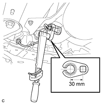
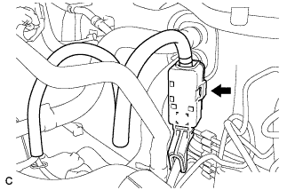
| 40. INSTALL HEATED OXYGEN SENSOR |
Using SST, install the oxygen sensor to the front exhaust pipe assembly.
- SST
- 09224-00010
- Момент затяжки:
- without SST:
- 44 Н*м{449 кгс*см, 32 фунт-сила-футов}
- with SST:
- 40 Н*м{408 кгс*см, 30 фунт-сила-футов}
- ПРИМЕЧАНИЕ:
- Use a torque wrench with a fulcrum length of 300 mm (11.81 in.)
- Do not damage the oxygen sensor.
 |
Connect the oxygen sensor connector.
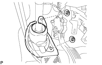
| 41. INSTALL NO. 1 STEERING COLUMN HOLE COVER SUB-ASSEMBLY |
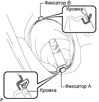 |
Установите фиксатор B на кузов, а также установите на кузов кожух выходного отверстия рулевой колонки № 1 в сборе и закрепите его фиксатором A.
- ПРИМЕЧАНИЕ:
- Убедитесь, что кромка кожуха выходного отверстия рулевой колонки №1 в сборе не повреждена.
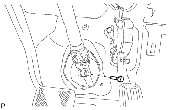
| 42. INSTALL NO. 2 STEERING INTERMEDIATE SHAFT ASSEMBLY |
Совместите метки на промежуточном валу № 2 рулевого управления в сборе и промежуточном валу рулевого управления в сборе.
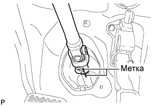 |
Заверните болт.
- Момент затяжки:
- 35 Н*м{360 кгс*см, 26 фунт-сила-футов}
 |
| 43. INSTALL COLUMN HOLE COVER SILENCER SHEET |
Установите шумоизолирующую накладку кожуха выходного отверстия рулевой колонки и закрепите ее 2 фиксаторами.
 |
Расправьте напольный коврик.
| 44. INSTALL WIRE HARNESS |
Install the earth wire to the engine room wire with the bolt and clamp (for Manual Transaxle).
- Момент затяжки:
- 13 Н*м{130 кгс*см, 10 фунт-сила-футов}
 |
Install the earth wire to the engine room wire with the bolt and clamp (for Automatic Transaxle).
- Момент затяжки:
- 26 Н*м{260 кгс*см, 19 фунт-сила-футов}
 |
Install the wire harness with the 2 nuts.
- Момент затяжки:
- 8.4 Н*м{85 кгс*см, 74 фунт-сила-дюймов}
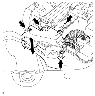 |
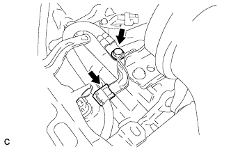
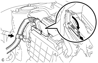
Connect the wire harness connector and wire harness clamp to the engine room junction block.
Connect the connector to the engine control computer with the clamp and lock lever.
 |
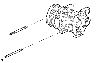
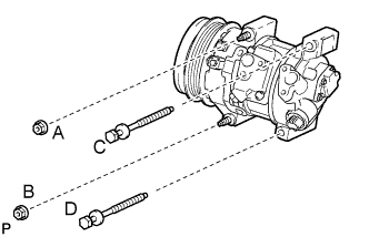
| 45. INSTALL COMPRESSOR WITH PULLEY ASSEMBLY (w/ Air Conditioning System) |
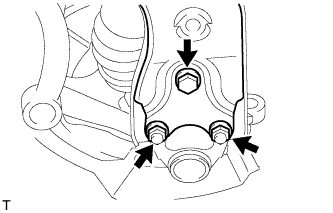
С помощью торцевого ключа со сменной головкой "TORX" (E8) установите компрессор со шкивом в сборе, закрепив его 2 шпильками.
- Момент затяжки:
- 9,8 Н*м{100 кгс*см, 7,2 фунт-сила-футов}
 |
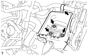
Закрепите компрессор со шкивом в сборе 2 болтами и 2 гайками.
- УКАЗАНИЕ:
- Затягивайте болты и гайки в порядке, показанном на рисунке.
- Момент затяжки:
- :
- 25 Н*м{255 кгс*см, 18,4 фунт-сила-футов}
 |
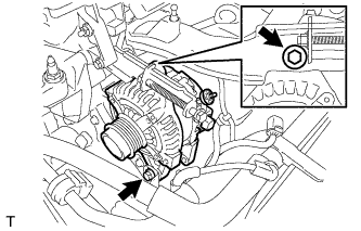
| 46. INSTALL GENERATOR ASSEMBLY |
Install the wire harness clamp bracket with the bolt.
- Момент затяжки:
- 8.4 Н*м{86 кгс*см, 74 фунт-сила-дюймов}
 |
Temporarily install the generator assembly with the 2 bolts.
 |
Install the wire harness to terminal B with the nut and install the terminal cap.
- Момент затяжки:
- 9.8 Н*м{100 кгс*см, 87 фунт-сила-дюймов}
 |
Install the connector and wire harness clamp.
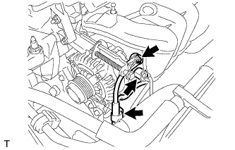
| 47. INSTALL V-RIBBED BELT |
Install the belt.
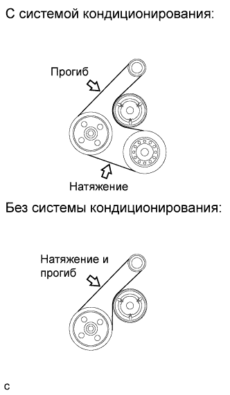
| 48. ADJUST V-RIBBED BELT |
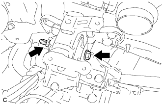
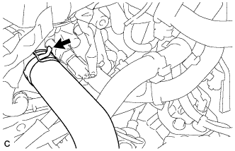
Turn bolt C to adjust the tension of the V-ribbed belt.
 |
Tighten bolts A and B.
- Момент затяжки:
- Bolt A:
- 19 Н*м{190 кгс*см, 14 фунт-сила-футов}
- Bolt B:
- 43 Н*м{438 кгс*см, 32 фунт-сила-футов}
- ПРИМЕЧАНИЕ:
- Do not loosen bolt D.
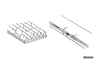
| 49. INSPECT V-RIBBED BELT |
Visually check the belt for excessive wear, frayed cords etc. If any defects are found, replace the belt.
- УКАЗАНИЕ:
- If any defects are found, replace the belt.
- Cracks on the rib side of a belt are considered acceptable. If the belt has pieces missing from the ribs, it should be replaced.
 |
After installing the drive belt, check that it fits properly in the ribbed grooves. Check with your hand to confirm that the belt has not slipped out of the grooves on the bottom of the crank pulley.
- УКАЗАНИЕ:
- A "new belt" is a belt which has been used for less than 5 minutes on a running engine.
- A "used belt" is a belt which has been used on a running engine for 5 minutes or more.
- After installing a new belt, run the engine for approximately 5 minutes and then recheck the tension.
 |
Check the V belt deflection and tension.
- Deflection:
Item Specified Condition New belt 7.5 to 8.6 mm (0.30 to 0.34 in.) Used belt 8.0 to 10.0 mm (0.32 to 0.39 in.)
- Tension:
Item Specified Condition New belt
(w/ A/C)688 to 940 N (70 to 96 kg, 155 to 211 lb) New belt
(w/o A/C)688 to 884 N (70 to 90 kg, 155 to 199 lb) Used belt 402 to 598 N (41 to 61 kg, 90 to 134 lb)
- УКАЗАНИЕ:
- Check the V belt deflection at the specified point.
- Check the drive belt deflection at the specified point.
- When installing a new belt, adjust its tension to the specified value.
- When inspecting a belt which has been used for over 5 minutes, apply the used belt specifications.
- When reinstalling a belt which has been used for over 5 minutes, adjust its deflection and tension to the intermediate values of each used belt specification.
- V-ribbed belt tension and deflection should be checked after 2 revolutions of engine cranking.
- When using a belt tension gauge, confirm its accuracy by using a master gauge first.
 |
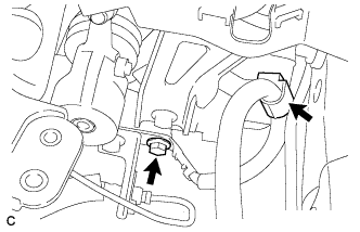
| 50. CONNECT FUEL TUBE SUB-ASSEMBLY |
Connect the fuel tube connector and fuel pipe.
- ПРЕДОСТЕРЕЖЕНИЕ:
- Align the fuel tube connector with the pipe, then push the fuel tube connector in until the retainer makes a "click" sound. If the connection is tight, apply a small amount of engine oil to the tip of the pipe. After connecting, pull the pipe and connector to make sure that they are securely connected.
Engage the claw and install the No. 1 fuel pipe clamp.
 |
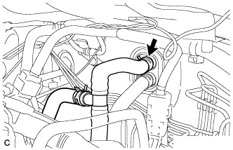
| 51. CONNECT HEATER INLET WATER HOSE |
Connect the heater inlet water hose with the clamp.
 |
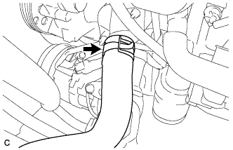
| 52. CONNECT HEATER OUTLET WATER HOSE |
Connect the heater outlet water hose with the clamp.
 |
| 53. CONNECT UNION TO CHECK VALVE HOSE |
Connect the union to check valve hose with the clamp.
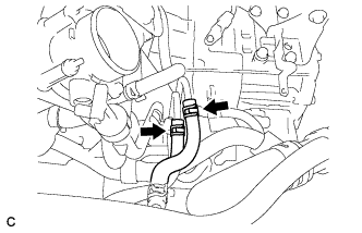
| 54. CONNECT OIL COOLER HOSE |
Connect the 2 oil cooler hoses with the clamp.
 |
| 55. INSTALL TRANSMISSION CONTROL CABLE ASSEMBLY |
Fix the control cable onto the control cable bracket with the clip.
 |
Connect the control cable onto the control shaft lever with the nut.
- Момент затяжки:
- 12 Н*м{122 кгс*см, 9 фунт-сила-футов}
Connect the control cable to the cable support.
Connect the clamp of the control cable with the bolt.
- Момент затяжки:
- 12 Н*м{122 кгс*см, 9 фунт-сила-футов}
| 56. CONNECT RADIATOR HOSE OUTLET |
Connect the radiator hose outlet with the clamp.
 |
| 57. CONNECT RADIATOR HOSE INLET |
Connect the radiator hose inlet with the clamp.
 |
| 58. INSTALL BATTERY CARRIER |
Install the battery carrier with the 4 bolts.
- Момент затяжки:
- 19 Н*м{190 кгс*см, 14 фунт-сила-футов}
Connect the water pipe with the 2 bolts.
- Момент затяжки:
- 19 Н*м{190 кгс*см, 14 фунт-сила-футов}
 |
Connect the 2 wire harness clamps.
 |
| 59. INSTALL BATTERY |
Install the battery clamp.
- Момент затяжки:
- for bolt:
- 17 Н*м{168 кгс*см, 12 фунт-сила-футов}
- for nut:
- 3.5 Н*м{36 кгс*см, 31 фунт-сила-дюймов}
Install the battery terminal.
- Момент затяжки:
- 5.4 Н*м{55 кгс*см, 48 фунт-сила-дюймов}
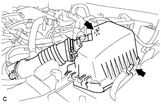
| 60. INSTALL AIR CLEANER CASE |
Install the air cleaner case with the 3 bolts.
- Момент затяжки:
- 7.0 Н*м{71 кгс*см, 62 фунт-сила-дюймов}
 |
Install the wire harness clamp to the air cleaner case.
Install the air cleaner filter element.
| 61. REMOVE AIR CLEANER CAP SUB-ASSEMBLY |
Connect the air cleaner cap sub-assembly with the band.
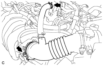 |
Connect the ventilation hose.
Connect the 2 clamps.
 |
Connect the mass air flow meter connector.
| 62. INSTALL FRONT WHEELS |
- Момент затяжки:
- 103 Н*м{1050 кгс*см, 76 фунт-сила-футов}
| 63. ADD ENGINE COOLANT |
Tighten the radiator drain cock plug.
Tighten the cylinder block drain cock plug.
- Момент затяжки:
- 13 Н*м{130 кгс*см, 9 фунт-сила-футов}
Add TOYOTA Super Long Life Coolant (SLLC) to the radiator reservoir filler opening.
- Standard capacity:
Item Capacity Engine coolant for manual transaxle:
5.6 liters (5.9 US qts, 4.9 lmp. qts)for automatic transaxle:
5.5 liters (5.8 US qts, 4.8 lmp. qts)
- УКАЗАНИЕ:
- TOYOTA vehicles are filled with TOYOTA SLLC at the factory. In order to avoid damage to the engine cooling system and other technical problems, only use TOYOTA SLLC or similar high quality ethylene glycol based non-silicate, non-amine, non-nitrite, non-borate coolant with long-life hybrid organic acid technology (coolant with long-life hybrid organic acid technology consists of a combination of low phosphates and organic acids).
- Contact your TOYOTA dealer for further details.
- ПРИМЕЧАНИЕ:
- Never use water as a substitute for engine coolant.
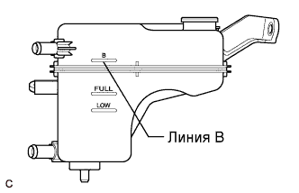
Remove the radiator cap and add coolant to line B of the reservoir tank.
 |
Squeeze the inlet and outlet radiator hoses several times by hand, and then check the level of the coolant.
If the coolant level is low, add coolant.
Install the cap and valve, and warm up the engine sufficiently.
Bleed air from the cooling system.
- ПРИМЕЧАНИЕ:
- Before starting the engine, turn the A/C switch OFF.
- Adjust the air conditioner set temperature to MAX (HOT).
- Adjust the air conditioner set blower to Lo.
Warm up the engine until the thermostat opens. While the thermostat is open, allow the coolant to circulate for several minutes.
- УКАЗАНИЕ:
- The thermostat opening timing can be confirmed by squeezing the inlet radiator hose by hand, and sensing vibrations when the engine coolant starts to flow inside the hose.
- ПРЕДОСТЕРЕЖЕНИЕ:
- When squeezing the radiator hose:
- Wear protective gloves.
- Be careful as the radiator hoses are hot.
- Keep your hands away from the radiator fan.
After the engine has warmed up, run the engine using the following cycle for at least 7 minutes: at 3000 rpm for 5 seconds, at idle speed for 45 seconds. (Repeat this cycle at least 8 times.)
Squeeze the inlet and outlet radiator hoses several times by hand to bleed air from the system.
- ПРЕДОСТЕРЕЖЕНИЕ:
- When squeezing the radiator hose:
- Wear protective gloves.
- Be careful as the radiator hoses are hot.
- Keep your hands away from the radiator fan.
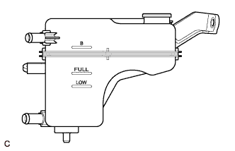
After the engine has cooled down, check that the coolant level is between FULL and LOW.
If the coolant level is low, add coolant to the FULL line on the reservoir tank.
 |
| 64. ADD AUTOMATIC TRANSAXLE FLUID |
- Fluid type:
- Toyota Genuine ATF WS
- Capacity:
- 2.9 liters (3.1 US qts, 2.6 lmp.qts)
| 65. INSPECT AUTOMATIC TRANSAXLE FLUID |
- УКАЗАНИЕ:
- Drive the vehicle so that the engine and transaxle are at normal operating temperature.
- Fluid temperature:
- 70 to 80°C (158 to 176°F)
Park the vehicle on a level surface and set the parking brake.
 |
With the engine idling and the brake pedal depressed, move the shift lever to all positions from the P position to L position. Then return it to the P position.
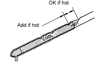
Pull out the dipstick and wipe it clean.
Push it back fully into the pipe.
Pull it out again and check that the fluid level is within the HOT range. If the fluid level is below the HOT range, add new fluid and recheck the fluid level. If the fluid level exceeds the HOT range, drain the fluid once, add proper amount of new fluid and recheck the fluid level.
| 66. INSPECT FOR TRANSAXLE FLUID LEAK |
| 67. INSPECT FOR FUEL LEAK |
Check fuel pump operation.
Connect the intelligent tester to the DLC3.
Turn the ignition switch on (IG) and turn the intelligent tester main switch on.
- ПРИМЕЧАНИЕ:
- Do not start the engine.
Select the following menus: Powertrain / Engine / Active Test / Control the Fuel Pump /Speed.
Check for pressure in the fuel inlet tube from the fuel line. Check that sound of fuel flowing in the fuel tank can be heard. If no sound can be heard, check the integration relay, fuel pump, ECM and wiring connector.
Inspect for fuel leak.
Check that there are no fuel leaks anywhere on the system after performing maintenance. If there is a fuel leak, repair or replace parts as necessary.
Turn the ignition switch off.
Disconnect the intelligent tester from the DLC3.
| 68. INSPECT FOR ENGINE COOLANT LEAK |
- ПРЕДОСТЕРЕЖЕНИЕ:
- To avoid the danger of being burned, do not remove the radiator cap sub-assembly while the engine and radiator assembly are still hot. Thermal expansion will cause hot engine coolant and steam to blow out from the radiator assembly.
Fill the radiator assembly with engine coolant, then attach a radiator cap tester.
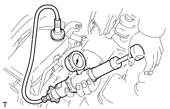 |
Pump it to 108 kPa (1.1 kgf/cm2, 15.6 psi), then check that the pressure does not drop.
If the pressure drops, check the hoses, radiator assembly and water pump assembly for leakage. If there are no signs or traces of external engine coolant leakage, check the heater core, cylinder block and head.
| 69. INSPECT FOR OIL LEAK |
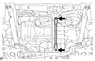
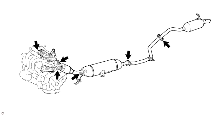
| 70. INSPECT FOR EXHAUST GAS LEAK |
Check that there are no exhaust gas leaks from the points (joints of the exhaust pipes and installation points of each sensor) shown in the illustration.
| 71. ADJUST SHIFT LEVER POSITION (for Sedan) |
Apply the parking brake and move the shift lever to the N position.
Remove the rear console box assembly (See page Нажмите здесь).
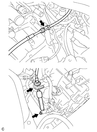
Disconnect the end of the transmission control cable assembly from the shift lever assembly.
 |
Using a screwdriver, pull out the stopper of the transmission control cable.
- ПРИМЕЧАНИЕ:
- Do not remove the stopper. If the stopper is removed, reinstall it to its original position.
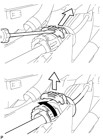 |
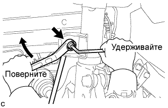
Rotate the nut counterclockwise approximately 180° and, while holding the nut in that position, disconnect the transmission control cable from the shift lever retainer.
- ПРИМЕЧАНИЕ:
- Do not over-rotate the nut as it will come off the interior spring and the transmission control cable will not be reusable.
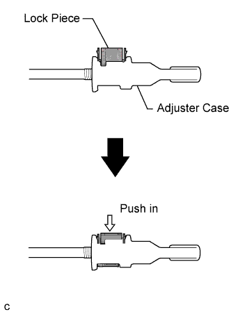
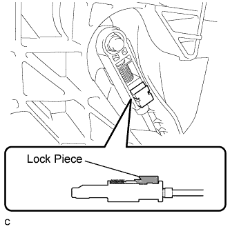
Push the two claws together at the top of the transmission control cable lock piece. While holding the two claws together, push the two lugs on the bottom of the lock piece toward each other and upward to pull out the lock piece.
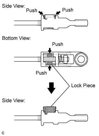 |
Turn the nut of the transmission control cable 180° counterclockwise. While holding the nut in place, push in the stopper until the stopper clicks twice.
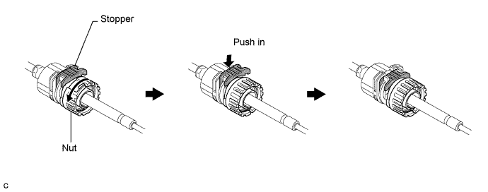
Install the outer part of the transmission control cable to the shift lever retainer. Check that the spring is positioned at "A" and push in the stopper.

- УКАЗАНИЕ:
- If the stopper cannot be pushed in, slightly turn the nut clockwise and then push in the stopper again.
Install the cable end to the shift lever assembly.
- ПРИМЕЧАНИЕ:
- Check that the lock piece is pulled up.
- Install the cable end all the way to the base of the pin.
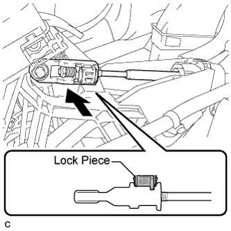 |
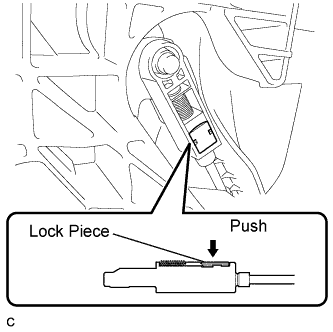
Push the lock piece into the adjuster case.
- ПРИМЕЧАНИЕ:
- Securely push in the lock piece until it locks.
 |
After adjusting the shift lever position, check the operation and function of the shift lever. If there is a problem, adjust the position again.
Install the rear console box assembly (See page Нажмите здесь).
| 72. ADJUST SHIFT LEVER POSITION (for Hatchback) |
Apply the parking brake and move the shift lever to the N position.
Remove the lower instrument panel finish panel (See page Нажмите здесь).
Disconnect the end of the transmission control cable assembly from the shift lever assembly.
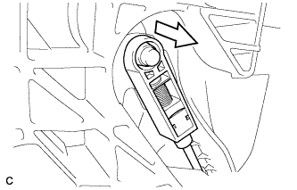 |
Turn the lock nut counterclockwise. While holding the lock nut, disconnect the transmission control cable from the shift lever retainer.
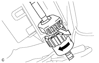 |
Slide the slider of the transmission control cable in the direction indicated by the arrow and pull the lock piece outward.
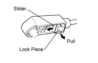 |
Connect the outer part of the transmission control cable to the shift lever retainer.
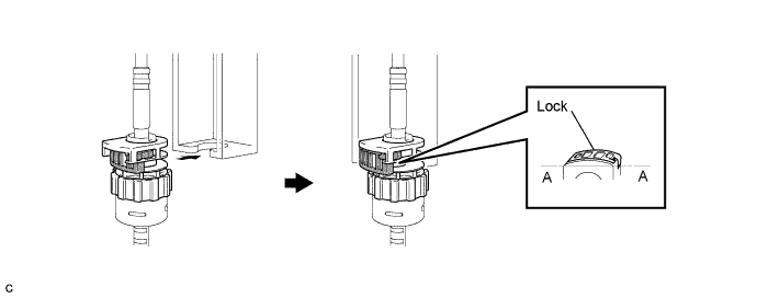
- УКАЗАНИЕ:
- After installation, check that the outer part of the cable protrudes above the A-A line as shown in the illustration.
Install the transmission control cable end to the shift lever assembly.
- ПРИМЕЧАНИЕ:
- Check that the lock piece is pulled outward.
- Install the cable end all the way to the base of the pin.
 |
Push the lock piece into the adjuster case.
- ПРИМЕЧАНИЕ:
- Securely push in the lock piece until the slider lock is engaged.
 |
After adjusting the shift lever position, check that the operation and function of the shift lever. If there is a problem, adjust the position again.
Install the lower instrument panel finish panel (See page Нажмите здесь).
| 73. INSPECT SHIFT LEVER POSITION |
When moving the lever from the P position to the R position with the ignition switch on (IG) and the brake pedal depressed, make sure that the shift lever moves smoothly and moves correctly into position.
Start the engine and make sure that the vehicle moves forward when moving the lever from the N position to the D position and moves rearward when moving the lever to the R position. If the operation cannot be performed as specified, inspect the park/neutral position switch assembly and check the shift lever assembly installation condition.
| 74. INSTALL NO. 2 ENGINE UNDER COVER |
| 75. INSTALL NO. 1 ENGINE UNDER COVER |
| 76. INSTALL REAR ENGINE UNDER COVE LH |
| 77. INSTALL REAR ENGINE UNDER COVER RH |
| 78. INSPECT IGNITION TIMING |
When using an intelligent tester:
Warm up and stop the engine.
Connect the intelligent tester to the DLC3.
Turn the ignition switch on (IG).
Select the following menu items:
Powertrain / Engine and ECT / Active Test / TC (TE1) / ON.- УКАЗАНИЕ:
- Refer to the intelligent tester operator's manual for further details.
Inspect the ignition timing during idling.
- Ignition timing:
- 8 to 12 degrees BTDC
- ПРИМЕЧАНИЕ:
- Turn all the electrical systems and the A/C off.
- Inspect the ignition timing with the cooling fan off.
- When checking the ignition timing, shift the transmission to the neutral position.
Select the following menu items: TC (TE1) / OFF.
Turn the ignition switch off.
Disconnect the intelligent tester from the DLC3.
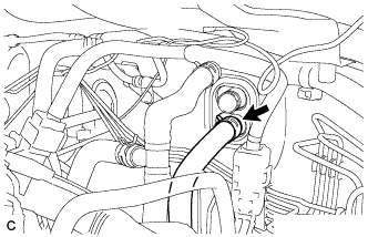
When not using an intelligent tester:
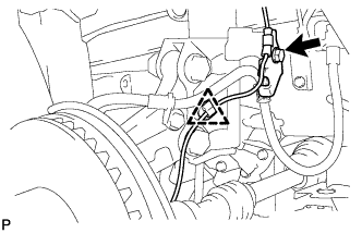
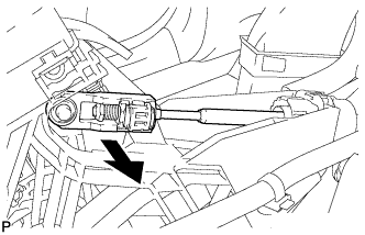
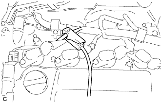
Remove the No. 2 cylinder head cover (See page Нажмите здесь).
Pull out the wire harness (brown) shown in the illustration.
- ПРИМЕЧАНИЕ:
- After checking, wrap the wire harness with tape.
Warm up and stop the engine.
Connect the clip of the timing light to the wire harness.
- ПРИМЕЧАНИЕ:
- Use a timing light that detects the first signal.
Turn the ignition switch on (IG).
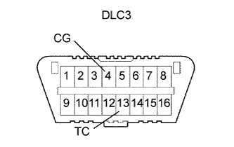
Using SST, connect terminals 13 (TC) and 4 (CG) of the DLC3.
- SST
- 09843-18040
- ПРИМЕЧАНИЕ:
- Examine the terminal numbers before connecting them. Connecting the wrong terminals can damage the engine.
Inspect the ignition timing during idling.
- Ignition timing:
- 8 to 12 degrees BTDC
- ПРИМЕЧАНИЕ:
- Turn all the electrical systems and the A/C off.
- Inspect the ignition timing with the cooling fan off.
- When checking the ignition timing, shift the transmission to the neutral position.
Disconnect terminals 13 (TC) and 4 (CG) of the DLC3.
Turn the ignition switch off.
Remove the timing light.
Install the No. 2 cylinder head cover (See page Нажмите здесь).
| 79. INSPECT ENGINE IDLE SPEED |
Warm up and stop the engine.
Connect the intelligent tester to the DLC3.
Turn the ignition switch on (IG).
Select the following menu items: Powertrain / Engine and ECT / Data List / Engine Speed.
- УКАЗАНИЕ:
- Refer to the intelligent tester operator's manual for further details.
Inspect the engine idling speed.
- Idling speed:
- 600 to 700 rpm
- ПРИМЕЧАНИЕ:
- Turn all the electrical systems and the A/C off.
- Inspect the idling speed with the cooling fan off.
- When checking the idling speed, shift the transmission to either the neutral position or the parking position.
Turn the ignition switch off.
Disconnect the intelligent tester from the DLC3.
| 80. INSPECT CO/HC |
Start the engine.
Run the engine at 2500 rpm for approximately 180 seconds.
Insert the CO/HC meter testing probe at least 40 cm (1.3 ft.) into the tailpipe while idling.
Check the CO/HC concentration during idling and when the engine is running at 2500 rpm.
- УКАЗАНИЕ:
- When doing the 2 mode (with the engine idling/ running at 2500 rpm) test, the measuring procedures are determined by applicable local regulations.
- If the CO/HC concentration does not comply with the regulations, troubleshoot in the order given below.
Check the heated oxygen sensor operation (See page Нажмите здесь).
See the table below for possible causes, then inspect the applicable parts and repair them if necessary.
CO HC Problems Possible Causes Normal High Rough idling - Faulty ignition:
- Incorrect timing
- Fouled, shorted or improperly gapped plugs
- Incorrect valve clearance
- Leakage from intake and exhaust valves
- Leakage from cylinders
Low High Rough idling (Fluctuating HC reading) - Vacuum leaks:
- PCV hoses
- Intake manifold
- Throttle body
- Brake booster line
- Lean mixture causing misfire
High High Rough idling (Black smoke from exhaust) - Restricted air cleaner filter element
- Plugged PCV valve
- Faulty EFI systems:
- Faulty pressure regulator
- Faulty engine coolant temperature sensor
- Faulty mass air flow meter
- Faulty ECM
- Faulty injectors
- Throttle body
- Faulty ignition:
| 81. INSPECT AND ADJUST FRONT WHEEL ALIGNMENT |
- УКАЗАНИЕ:
- (See page Нажмите здесь)
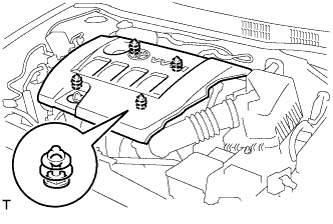
| 82. INSTALL NO. 2 CYLINDER HEAD COVER |
Engage the 4 clips to install the V-bank cover.
- ПРИМЕЧАНИЕ:
- Be sure to engage the clips securely.
- Do not apply excessive force or do not hit the cover to engage the clips. This may cause the cover to break.
 |
| 83. INSTALL UPPER RADIATOR AIR DEFLECTOR |
| 84. PERFORM INITIALIZATION |
- УКАЗАНИЕ:
- (See page Нажмите здесь)
| 85. CHECK ABS SPEED SENSOR SIGNAL |
ABS: Нажмите здесь for TMC made
VSC: Нажмите здесь for TMC made