INSPECT EXHAUST FUEL ADDITION INJECTOR ASSEMBLY
CHECK HARNESS AND CONNECTOR (EXHAUST FUEL ADDITION INJECTOR ASSEMBLY - ECM)
CHECK HARNESS AND CONNECTOR (EXHAUST FUEL ADDITION INJECTOR ASSEMBLY - EFI MAIN RELAY)
DTC P2047 Reductant Injector Circuit / Open (Bank 1 Unit 1) |
DTC P2048 Short to GND in Reductant Injector Circuit (Bank 1) |
DTC P2049 Short to B+ in Reductant Injector Circuit (Bank 1) |
DESCRIPTION
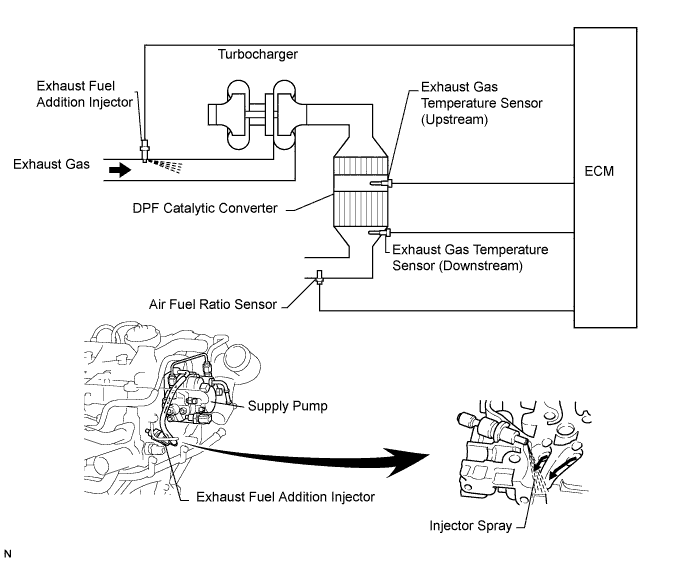
The exhaust fuel addition injector is mounted on the exhaust port of the cylinder head, and low pressure is provided to the injector by the feed pump in the supply pump. This injector adds fuel by a control signal from the ECM.
This injector is used for DPF catalyst regeneration.
Under the DPF catalyst regeneration control, the injector adds fuel to raise a catalyst temperature.
- УКАЗАНИЕ:
- For more information on the exhaust fuel addition injector and DPF (*1) system: (See page Нажмите здесь)
- If P2047, P2048 and P2049 are present, refer to the DTC table for DPF system (See page Нажмите здесь).
- *1: Diesel Particulate Filter
| DTC No. | DTC Detection Condition | Trouble Area |
| P2047 | With the exhaust fuel addition injector off, the FIVM1 output is high and the FIVM2 output is low for 3 seconds. (1-trip detection logic) |
|
| P2048 | With the exhaust fuel addition injector off, the FIVM1 output is high and the FIVM2 output is high for 0.16 seconds. (1-trip detection logic) | |
| P2049 | With the exhaust fuel addition injector on, the FIVM1 output is low and the FIVM2 output is low for 7 or more times. (1-trip detection logic) |
- УКАЗАНИЕ:
- DTC P1386 (injector for exhaust fuel addition) will be present if there is an open in the exhaust fuel addition injector circuit.
MONITOR DESCRIPTION
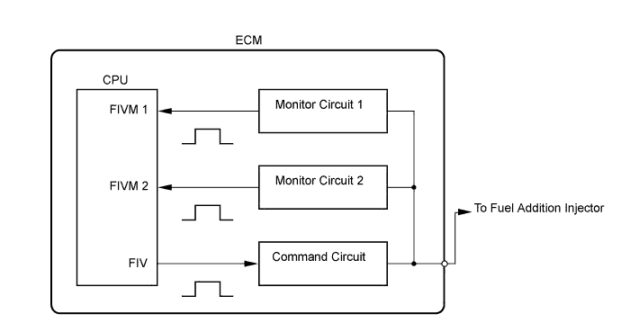
In order to detect abnormality in the fuel addition injector, an internal CPU of the ECM monitors injection command (FIV) signals and injection confirmation (FIVM) signals. The FIV signal is sent from the CPU to the (exhaust) fuel addition injector via a drive circuit inside the ECM. The FIVM signal, which is originally output current from the internal drive circuit of the ECM, is transmitted to the CPU via a monitor circuit. By receiving the FIVM signal, the ECM judges that the current has been applied to the (exhaust) fuel addition injector.This DTC will be set if the ECM judges that the number of signals of the FIV and the FIVM are inconsistent.
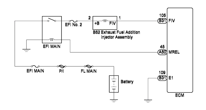
WIRING DIAGRAM
INSPECTION PROCEDURE
- ПРИМЕЧАНИЕ:
- After replacing the ECM, the new ECM needs registration (See page Нажмите здесь) and initialization (See page Нажмите здесь).
- УКАЗАНИЕ:
- Read freeze frame data using the intelligent tester. The ECM records vehicle and driving condition information as freeze frame data the moment a DTC is stored. When troubleshooting, freeze frame data can help determine if the vehicle was moving or stationary, if the engine was warmed up or not, and other data from the time the malfunction occurred.
| 1.INSPECT EXHAUST FUEL ADDITION INJECTOR ASSEMBLY |
Disconnect the exhaust fuel addition injector connector.
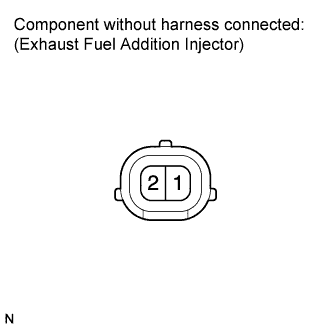 |
Measure the resistance according to the value(s) in the table below.
- Standard resistance:
Tester Connection Condition Specified Condition 1 - 2 20°C (68°F) 7.1 to 7.9 Ω
Reconnect the exhaust fuel addition injector connector.
|
| ||||
| OK | |
| 2.CHECK FUSE (EFI NO. 2 FUSE) |
Remove the EFI No. 2 fuse from the engine room relay block.
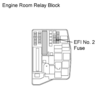 |
Measure the resistance according to the value(s) in the table below.
- Standard resistance:
Tester Connection Condition Specified Condition EFI No. 2 fuse Always Below 1 Ω
Reinstall the EFI No. 2 fuse.
|
| ||||
| OK | |
| 3.CHECK HARNESS AND CONNECTOR (EXHAUST FUEL ADDITION INJECTOR ASSEMBLY - ECM) |
Disconnect the exhaust fuel addition injector assembly connector.
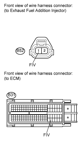 |
Disconnect the ECM connector.
Measure the resistance according to the value(s) in the table below.
- Standard resistance (Check for open):
Tester Connection Condition Specified Condition B52-1 (FIV) - B31-105 (FIV) Always Below 1 Ω
- Standard resistance (Check for short):
Tester Connection Condition Specified Condition B52-1 (FIV) or B31-105 (FIV) - Body ground Always 10 kΩ or higher
Reconnect the exhaust fuel addition injector assembly connector.
Reconnect the ECM connector.
|
| ||||
| OK | |
| 4.CHECK HARNESS AND CONNECTOR (EXHAUST FUEL ADDITION INJECTOR ASSEMBLY - EFI MAIN RELAY) |
Disconnect the exhaust fuel addition injector assembly connector.
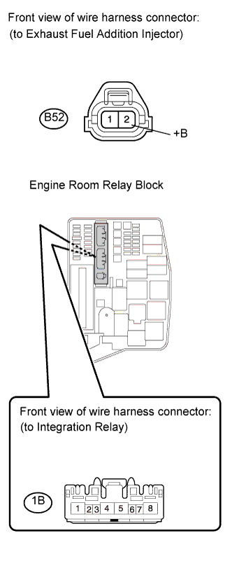 |
Remove the integration relay from the engine room relay block.
Disconnect the integration relay connector.
Measure the resistance according to the value(s) in the table below.
- Standard resistance (Check for open):
Tester Connection Condition Specified Condition B52-2 (+B) - 1B-4 Always Below 1 Ω
- Standard resistance (Check for short):
Tester Connection Condition Specified Condition B52-2 (+B) or 1B-4 - Body ground Always 10 kΩ or higher
Reconnect the exhaust fuel addition injector assembly connector.
Reconnect the integration relay connector.
Reinstall the integration relay.
|
| ||||
| OK | ||
| ||