CHECK OTHER DTC OUTPUT (IN ADDITION TO DTC P2237)
INSPECT AIR FUEL RATIO SENSOR (HEATER RESISTANCE)
CHECK HARNESS AND CONNECTOR (AIR FUEL RATIO SENSOR - ECM)
DTC P2237 Oxygen (A/F) Sensor Pumping Current Circuit / Open (Bank 1 Sensor 1) |
DTC P2238 Oxygen (A/F) Sensor Pumping Current Circuit Low (Bank 1 Sensor 1) |
DTC P2239 Oxygen (A/F) Sensor Pumping Current Circuit High (Bank 1 Sensor 1) |
DTC P2252 Oxygen (A/F) Sensor Reference Ground Circuit Low (Bank 1 Sensor 1) |
DTC P2253 Oxygen (A/F) Sensor Reference Ground Circuit High (Bank 1 Sensor 1) |
DESCRIPTION
- УКАЗАНИЕ:
- For more information on the air fuel ratio sensor and TOYOTA D-CAT*: (See page Нажмите здесь).
- This DTC is related to the air fuel ratio sensor, although the caption is the oxygen sensor.
- If P2237, P2238 and/or P2239 is present, refer to the DTC table for the TOYOTA D-CAT system (See page Нажмите здесь).
- These DTCs are recorded when the air fuel ratio sensor has a malfunction, although the caption is the oxygen sensor.
- *: Diesel Clean Advanced Technology
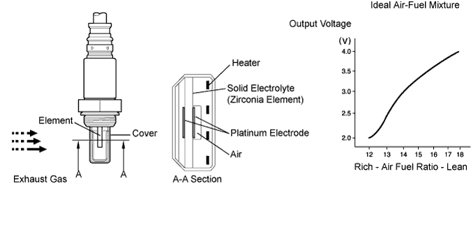
The air fuel ratio sensor is located after the DPF (*2) catalytic converter. This sensor has been developed based on structure and technology of a sensor that is being used for gasoline engines. The cover portion of the sensor has been changed for use in the diesel engine with TOYOTA D-CAT in order to eliminate the influence of the sensor temperature and particulate matter (PM).
In order to reduce PM, the ECM adjusts the air fuel ratio to slightly RICH (but it is LEAN compared with a stoichiometric air fuel ratio) based on signals from the air fuel ratio sensor. When the ECM exercises DPF catalyst regeneration by adding fuel using the exhaust fuel addition injector, the air fuel ratio is also properly adjusted through the sensor.
*1: The voltage value changes inside the ECM only.
*2: Diesel Particulate Filter
- УКАЗАНИЕ:
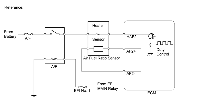
- The ECM provides a pulse width modulated control circuit to adjust current through the heater. The air fuel ratio sensor heater circuit uses a relay on the B+ side of the circuit.
| DTC No. | DTC Detection Condition | Trouble Area |
| P2237 | ECM internal error (5.0 seconds) (1-trip detection logic) | ECM |
| P2238 P2252 | Air fuel ratio sensor circuit low (bank 1 sensor 1) AF+ is less than 1.0 V for 5.0 seconds or more (1-trip detection logic) | Main trouble area: Open in air fuel ratio sensor circuit
|
| P2239 P2253 | Air fuel ratio sensor circuit high (bank 1 sensor 1) AF+ is more than 4.0 V for 5.0 seconds or more (1-trip detection logic) | Main trouble area: Short in air fuel ratio sensor circuit
|
MONITOR DESCRIPTION
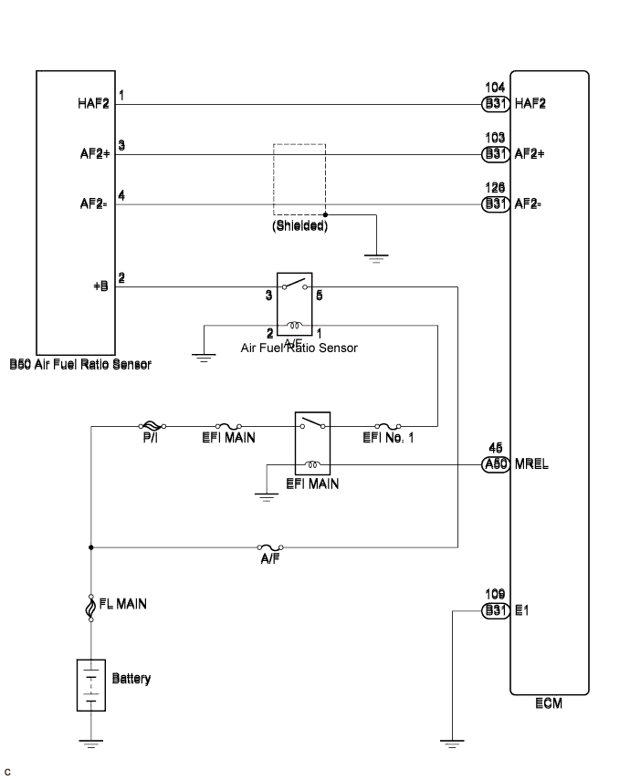
The air fuel ratio sensor varies its voltage output in proportion to the air-fuel ratio. If impedance (alternating current resistance) or voltage output of the sensor deviates greatly from the standard range, the ECM interprets this as an open or short in the air fuel ratio sensor circuit.WIRING DIAGRAM
INSPECTION PROCEDURE
- ПРИМЕЧАНИЕ:
- After replacing the ECM, the new ECM needs registration (See page Нажмите здесь) and initialization (See page Нажмите здесь).
- УКАЗАНИЕ:
- Read freeze frame data using the intelligent tester. The ECM records vehicle and driving condition information as freeze frame data the moment a DTC is stored. When troubleshooting, freeze frame data can help determine if the vehicle was moving or stationary, if the engine was warmed up or not, and other data from the time the malfunction occurred.
| 1.CHECK OTHER DTC OUTPUT (IN ADDITION TO DTC P2237) |
Connect the intelligent tester to the DLC3.
Turn the ignition switch on (IG).
Turn the tester on.
Enter the following menu items: Powertrain / Engine and ECT / DTC.
Read the DTCs.
- Result:
Result Proceed to DTC P2237 and "P2238, P2239, P2252 and/or P2253" are output A DTC P2237 is output B
|
| ||||
| A | |
| 2.INSPECT AIR FUEL RATIO SENSOR (HEATER RESISTANCE) |
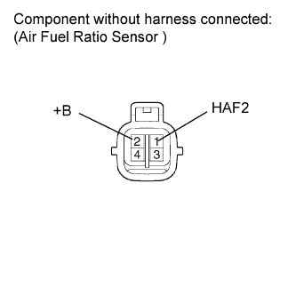
Disconnect the air fuel ratio sensor connector.
 |
Measure the resistance according to the value(s) in the table below.
- Standard resistance:
Tester Connection Condition Specified Condition 1 (HAF2) - 2 (+B) 20°C (68°F) 1.8 to 3.4 Ω
Reconnect the air fuel ratio sensor connector.
|
| ||||
| OK | |
| 3.INSPECT A/F RELAY |
Remove the A/F relay from engine room relay block.
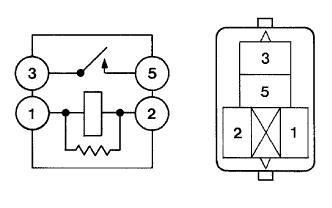 |
Measure the resistance according to the value(s) in the table below.
- Standard resistance:
Tester Connection Condition Specified Condition 3 - 5 Battery voltage is not applied between terminals 1 and 2 10 kΩ or higher Battery voltage is applied between terminals 1 and 2 Below 1 Ω
Reinstall the A/F relay.
|
| ||||
| OK | |
| 4.CHECK HARNESS AND CONNECTOR (AIR FUEL RATIO SENSOR - ECM) |
Disconnect the air fuel ratio sensor connector.
 |
Disconnect the ECM connector.
Measure the resistance according to the value(s) in the table below.
- Standard resistance (Check for open):
Tester Connection Condition Specified Condition B50-3 (AF2+) - B31-103 (AF2+) Always Below 1 Ω B50-4 (AF2-) - B31-126 (AF2-) Always Below 1 Ω B50-1 (HAF2) - B31-104 (HAF2) Always Below 1 Ω
- Standard resistance (Check for short):
Tester Connection Condition Specified Condition B50-3 (AF2+) or B31-103 (AF2+) - Body ground Always 10 kΩ or higher B50-4 (AF2-) or B31-126 (AF2-) - Body ground Always 10 kΩ or higher B50-1 (HAF2) or B31-104 (HAF2) - Body ground Always 10 kΩ or higher
Reconnect the air fuel ratio sensor connector.
Reconnect the ECM connector.
|
| ||||
| OK | ||
| ||