READ VALUE OF ACCELERATOR PEDAL POSITION SENSOR
CHECK HARNESS AND CONNECTOR (ACCELERATOR PEDAL POSITION SENSOR - ECM)
INSPECT ECM TERMINAL VOLTAGE (VCPA AND VCP2 TERMINALS)
CHECK WHETHER DTC OUTPUT RECURS
DTC P2120 Throttle / Pedal Position Sensor / Switch "D" Circuit |
DTC P2122 Throttle / Pedal Position Sensor / Switch "D" Circuit Low Input |
DTC P2123 Throttle / Pedal Position Sensor / Switch "D" Circuit High Input |
DTC P2125 Throttle / Pedal Position Sensor / Switch "E" Circuit |
DTC P2127 Throttle / Pedal Position Sensor / Switch "E" Circuit Low Input |
DTC P2128 Throttle / Pedal Position Sensor / Switch "E" Circuit High Input |
DTC P2138 Throttle / Pedal Position Sensor / Switch "D" / "E" Voltage Correlation |
DESCRIPTION
- УКАЗАНИЕ:
- This is the repair procedure for the accelerator pedal position sensor.
- This electrical throttle system does not use a throttle cable.
- This accelerator pedal position sensor is a non-contact type.
In the accelerator pedal position sensor, the voltage applied to pedal terminals VPA and VPA2 of the ECM changes between 0 V and 5 V in proportion to the opening angle of the accelerator pedal. The VPA is a signal to indicate the actual accelerator pedal opening angle which is used for the engine control, and the VPA2 is a signal to indicate the information about the opening angle which is used for detecting malfunctions. The ECM judges the current opening angle of the accelerator pedal using signals from terminals VPA and VPA2, and the ECM controls the throttle motor based on these signals.

| DTC No. | DTC Detection Condition (All of following are 1 trip detection logic) | Trouble Area |
| P2120 | Condition (a) continues for 0.5 sec. or more: (a) VPA is 0.4 V or less (b) VPA is 4.8 V or more |
|
| P2122 | VPA is 0.4 V or less for 0.5 sec. or more when VPA2 output indicates accelerator pedal is opened |
|
| P2123 | Condition (a) continues for 2.0 sec. or more: (a) VPA is 4.8 V or more |
|
| P2125 | Condition (a) or (b) continues for 0.5 sec. or more: (a) VPA2 is 1.2 V or less (b) VPA2 is 4.8 V or more |
|
| P2127 | VPA2 is 1.2 V or less for 0.5 sec. or more when VPA output indicates accelerator pedal is opened |
|
| P2128 | Conditions (a) and (b) continue for 2.0 sec. or more: (a) VPA2 is 4.8 V or more (b) VPA is 0.4 V or more and VPA is 3.45 V or less |
|
| P2138 | Condition (a) or (b) continues for 2.0 sec. or more: (a) Difference between VPA and VPA2 is 0.02 V or less (b) VPA is 0.4 V or less and VPA2 is 1.2 V or less |
|
- УКАЗАНИЕ:
- When DTC P2120, P2122, P2123, P2125, P2127, P2128, or P2138 is detected, check the output voltage of the accelerator pedal position sensor by entering the following menus on the intelligent tester: Powertrain / Engine and ECT / Data List / Accel Position 1 and Accel Position 2.
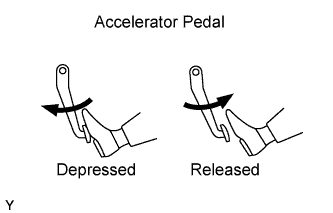
| - | Accelerator pedal position expressed as voltage output | |||
| Accelerator pedal released | Accelerator pedal depressed | |||
| Trouble Area | Accel position 1 | Accel position 2 | Accel position 1 | Accel position 2 |
| VCP circuit open | 0 to 0.2 V | 0 to 0.2 V | 0 to 0.2 V | 0 to 0.2 V |
| VPA circuit open or ground short | 0 to 0.2 V | 0.9 to 2.3 V | 0 to 0.2 V | 3.4 to 5.0 V |
| VPA2 circuit open or ground short | 0.5 to 1.1 V | 0 to 0.2 V | 3.0 to 4.6 V | 0 to 0.2 V |
| EP circuit open | 4.5 to 5.0 V | 4.5 to 5.0 V | 4.5 to 5.0 V | 4.5 to 5.0 V |
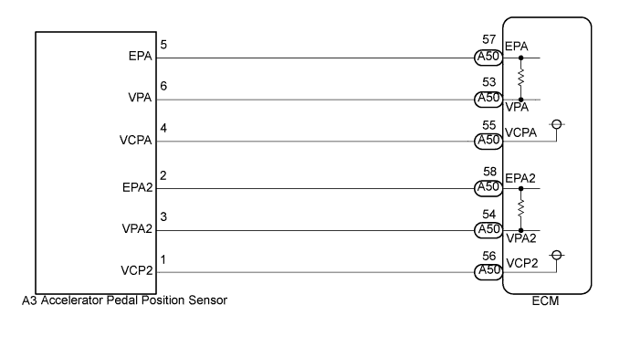
WIRING DIAGRAM
INSPECTION PROCEDURE
- ПРИМЕЧАНИЕ:
- After replacing the ECM, the new ECM needs registration (See page Нажмите здесь) and initialization (See page Нажмите здесь).
- УКАЗАНИЕ:
- Read freeze frame data using the intelligent tester. The ECM records vehicle and driving condition information as freeze frame data the moment a DTC is stored. When troubleshooting, freeze frame data can help determine if the vehicle was moving or stationary, if the engine was warmed up or not, and other data from the time the malfunction occurred.
| 1.READ VALUE OF ACCELERATOR PEDAL POSITION SENSOR |
Connect the intelligent tester to the DLC3.
 |
Turn the ignition switch on (IG) and turn the tester on.
Enter the following menus: Powertrain / Engine and ECT / Data List / Accel Position 1 and Accel Position 2.
Read the values.
- Standard voltage:
Accelerator Pedal Accel Position 1 Accel Position 2 Released 0.5 to 1.1 V 0.9 to 2.3 V Depressed 3.0 to 4.6 V 3.4 to 5.0 V
- Result:
Result Proceed to NG A OK B
|
| ||||
| A | |
| 2.CHECK HARNESS AND CONNECTOR (ACCELERATOR PEDAL POSITION SENSOR - ECM) |
Disconnect the accelerator pedal position sensor connector.
 |
Disconnect the ECM connector.
Measure the resistance according to the value(s) in the table below.
- Standard resistance (Check for open):
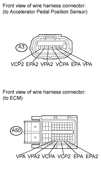
Tester Connection Condition Specified Condition A3-1 (VCP2) - A50-56 (VCP2) Always Below 1 Ω A3-2 (EPA2) - A50-58 (EPA2) Always Below 1 Ω A3-3 (VPA2) - A50-54 (VPA2) Always Below 1 Ω A3-4 (VCPA) - A50-55 (VCPA) Always Below 1 Ω A3-5 (EPA) - A50-57 (EPA) Always Below 1 Ω A3-6 (VPA) - A50-53 (VPA) Always Below 1 Ω
- Standard resistance (Check for short):
Tester Connection Condition Specified Condition A3-1 (VCP2) or A50-56 (VCP2) - Body ground Always 10 kΩ or higher A3-2 (EPA2) or A50-58 (EPA2) - Body ground Always 10 kΩ or higher A3-3 (VPA2) or A50-54 (VPA2) - Body ground Always 10 kΩ or higher A3-4 (VCPA) or A50-55 (VCPA) - Body ground Always 10 kΩ or higher A3-5 (EPA) or A50-57 (EPA) - Body ground Always 10 kΩ or higher A3-6 (VPA) or A50-53 (VPA) - Body ground Always 10 kΩ or higher
Reconnect the accelerator pedal position sensor connector.
Reconnect the ECM connector.
|
| ||||
| OK | |
| 3.INSPECT ECM TERMINAL VOLTAGE (VCPA AND VCP2 TERMINALS) |
Disconnect the accelerator pedal position sensor connector.
 |
Turn the ignition switch on (IG).
Measure the voltage according to the value(s) in the table below.
- Standard voltage:
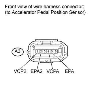
Tester Connection Switch Condition Specified Condition A3-4 (VCPA) - A3-5 (EPA) Ignition switch on (IG) 4.5 to 5.5 V A3-1 (VCP2) - A3-2 (EPA2) Ignition switch on (IG) 4.5 to 5.5 V
Reconnect the accelerator pedal position sensor connector.
|
| ||||
| OK | |
| 4.REPLACE ACCELERATOR PEDAL |
Replace the accelerator pedal (See page Нажмите здесь).
| NEXT | |
| 5.CHECK WHETHER DTC OUTPUT RECURS |
Connect the intelligent tester to the DLC3.
Turn the ignition switch on (IG) and turn the tester on.
Clear the DTCs (See page Нажмите здесь).
Leave it for approximately 1 minute.
Enter the following menus: Powertrain / Engine and ECT / DTC.
Read the DTCs.
- Result:
Result Proceed to DTC P2120, P2133, P2123, P2125, P2127, P2138 or P2138 are output A DTC is not output B
|
| ||||
| A | ||
| ||