READ VALUE USING INTELLIGENT TESTER
CHECK HARNESS AND CONNECTOR (BATTERY - BACK UP LIGHT SWITCH)
INSPECT BACK UP LIGHT SWITCH ASSEMBLY
CHECK HARNESS AND CONNECTOR (BACK UP LIGHT SWITCH - TCM)
CHECK HARNESS AND CONNECTOR (SHIFT STROKE SENSOR - TCM)
CHECK HARNESS AND CONNECTOR (SELECT STROKE SENSOR - TCM)
DTC P0812 Reverse Input Circuit |
DESCRIPTION
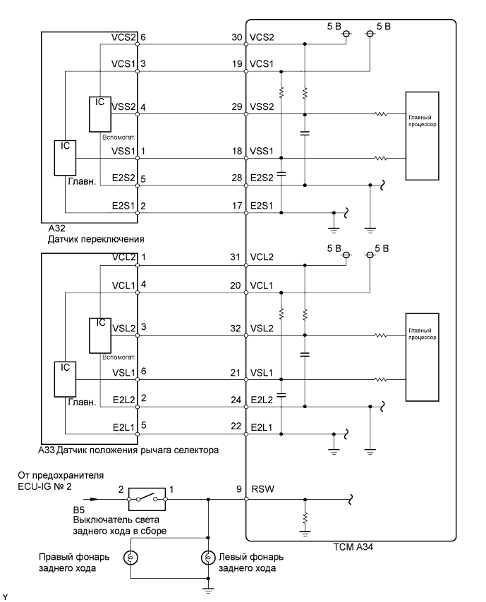
As one judgment method, the TCM uses the back up light switch signal indicating whether the gear is in reverse or not. Receiving the signals from the back up light switch assembly and the shift and select stroke sensors, the TCM detects that the transaxle gear is in reverse. If the signal from the back up light switch assembly does not match with the signal from the shift and select stroke sensors, the TCM sets the DTC.| DTC No. | DTC Detection Condition | Trouble Area |
| P0812 | The TCM detects the following conditions simultaneously: (1-trip detection logic)
|
|
| P0812 | The TCM detects the following conditions simultaneously: (1-trip detection logic)
|
|
WIRING DIAGRAM
INSPECTION PROCEDURE
- ПРИМЕЧАНИЕ:
- In shift and select stroke sensors replacement, perform [Initialization and Learning] and [Synchronization Position Calibration] after installing the sensors (See page Нажмите здесь).
- If the sensors are installed without performing [Initialization and Learning] and [Synchronization Position Calibration], it may cause driving performance degradation or system component breakage.
| 1.READ VALUE USING INTELLIGENT TESTER |
Connect the intelligent tester to the DLC3.
Turn the ignition switch on (IG) and the tester ON.
Select the following menu items: Powertrain / Multi-Mode M/T / Data List / T/M Reverse Switch Signal and Gear Position (Current).
Items
[Abbreviation]Measurement Items: Display Normal Conditions Diagnostic Notes T/M Reverse Switch Signal
[T/M R SW Sig]Transaxle reverse switch signal:
Open or GndGnd: Transaxle gear in reverse
Open: Other than aboveDuring malfunctions, indicator shows either ON or OFF continuously, regardless of gear position Gear Position (Current)
[Gear Pos-Cur]Current gear position:
Min.: 0, Max.: 7Actual gear position displayed 0 = Neutral
1 to 6 = 1st to 6th
7 = Reverse- OK:
- When the shift lever is operated, the normal condition listed above is shown on the tester.
- Result:
Result Proceed to NG A OK B
|
| ||||
| A | |
| 2.CHECK HARNESS AND CONNECTOR (BATTERY - BACK UP LIGHT SWITCH) |
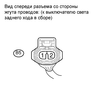
Disconnect the back up light switch connector.
 |
Turn the ignition switch on (IG).
Measure the voltage according to the value(s) in the table below.
- Standard voltage:
Tester Connection Switch Condition Specified Condition B5-2 - Body ground Ignition switch on (IG) 11 to 14 V
Reconnect the back up light switch connector.
|
| ||||
| OK | |
| 3.INSPECT BACK UP LIGHT SWITCH ASSEMBLY |
Remove the back up light switch assembly.
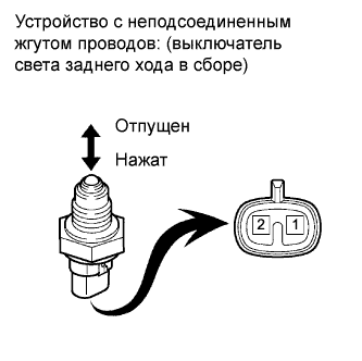 |
Check the resistance when the switch condition is released and pushed.
- Standard resistance:
Tester Connection Switch Condition Specified Condition 1-2 Released 10 kΩ or higher 1-2 Pushed Below 1 Ω
Reinstall the back up light switch assembly.
|
| ||||
| OK | |
| 4.CHECK HARNESS AND CONNECTOR (BACK UP LIGHT SWITCH - TCM) |
Disconnect the back up light switch assembly connector.
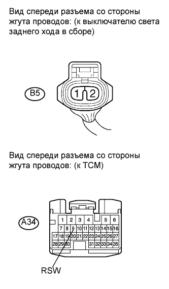 |
Disconnect the TCM connector.
Remove the back up light bulbs.
Measure the resistance according to the value(s) in the table below.
- Standard resistance:
Tester Connection Condition Specified Condition A34-9 (RSW) - B5-1 Always Below 1 Ω A34-9 (RSW) - Body ground ↑ 10 kΩ or higher
Turn the ignition switch on (IG).
Reconnect the back up light switch assembly connector.
Reconnect the TCM connector.
|
| ||||
| OK | |
| 5.INSPECT SHIFT STROKE SENSOR |
Remove the shift stroke sensor.
 |
Measure the voltage between the terminals of the shift stroke sensor connector (main).
Prepare 3 dry cell batteries (1.5 V) and 2 leads for connecting the batteries and the sensor.
Connect the batteries in series.
Connect the positive battery terminal to sensor terminal 3, and the negative battery terminal to sensor terminal 2.
Check the voltage between terminals 1 and 2.
- Standard voltage (combined dry cell battery voltage of 4.5 V):
Sensor Angle Terminal (1-2) Output Voltage 55° Approximately 4.05 V 0° Approximately 2.25 V -55° Approximately 0.45 V
- Reference voltage (combined dry cell battery voltage of 5.0 +- 0.3 V):
Sensor Angle Terminal (1-2) Output Voltage 55° Approximately 4.5 V 0° Approximately 2.5 V -55° Approximately 0.5 V
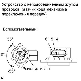
Measure the voltage between the terminals of the shift stroke sensor connector (sub).
Connect the positive battery terminal to sensor terminal 6, and the negative battery terminal to sensor terminal 5.
Check the voltage between terminals 4 and 5.
- Standard voltage (combined dry cell battery voltage of 4.5 V):
Sensor Angle Terminal (4-5) Output Voltage 55° Approximately 4.05 V 0° Approximately 2.25 V -55° Approximately 0.45 V
- Reference voltage (combined dry cell battery voltage of 5.0 +- 0.3 V):
Sensor Angle Terminal (4-5) Output Voltage 55° Approximately 4.5 V 0° Approximately 2.5 V -55° Approximately 0.5 V
- ПРИМЕЧАНИЕ:
- Do not apply more than 6 V
- Do not use a sensor which has been dropped.
 |
Reinstall the shift stroke sensor (See page Нажмите здесь).
Perform [Initialization and Learning] (See page Нажмите здесь) and [Synchronization Position Calibration] (See page Нажмите здесь).
|
| ||||
| OK | |
| 6.CHECK HARNESS AND CONNECTOR (SHIFT STROKE SENSOR - TCM) |
Disconnect the shift stroke sensor connector.
 |
Disconnect the TCM connector.
Measure the resistance according to the value(s) in the table below.
- Standard resistance:
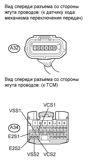
Tester Connection Condition Specified Condition A34-30 (VCS2) - A32-6 Always Below 1 Ω A34-29 (VSS2) - A32-4 ↑ Below 1 Ω A34-28 (E2S2) - A32-5 ↑ Below 1 Ω A34-19 (VCS1) - A32-3 ↑ Below 1 Ω A34-18 (VSS1) - A32-1 ↑ Below 1 Ω A34-17 (E2S1) - A32-2 ↑ Below 1 Ω A34-30 (VCS2) - Body ground ↑ 10 kΩ or higher A34-29 (VSS2) - Body ground ↑ 10 kΩ or higher A34-28 (E2S2) - Body ground ↑ 10 kΩ or higher A34-19 (VCS1) - Body ground ↑ 10 kΩ or higher A34-18 (VSS1) - Body ground ↑ 10 kΩ or higher A34-17 (E2S1) - Body ground ↑ 10 kΩ or higher
Reconnect the shift stroke sensor connector.
Reconnect the TCM connector.
|
| ||||
| OK | |
| 7.INSPECT SELECT STROKE SENSOR |
Remove the select stroke sensor.
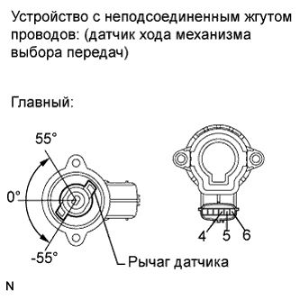 |
Measure the voltage between the terminals of the select stroke sensor connector (main).
Prepare 3 dry cell batteries (1.5 V) and 2 leads for connecting the batteries and the sensor.
Connect the batteries in series.
Connect the positive battery terminal to sensor terminal 4, and the negative battery terminal to sensor terminal 5.
Check the voltage between terminals 6 and 5.
- Standard voltage (combined dry cell battery voltage of 4.5 V):
Sensor Angle Terminal (6-5) Output Voltage 55° Approximately 4.05 V 0° Approximately 2.25 V -55° Approximately 0.45 V
- Reference voltage (combined dry cell battery voltage of 5.0 +- 0.3 V):
Sensor Angle Terminal (6-5) Output Voltage 55° Approximately 4.5 V 0° Approximately 2.5 V -55° Approximately 0.5 V
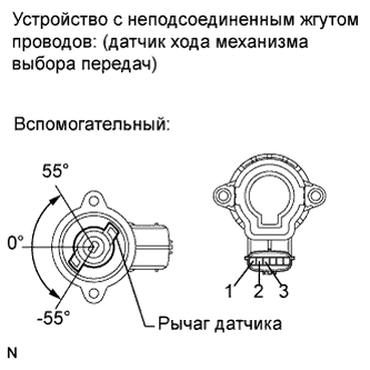
Measure the voltage between the terminals of the select stroke sensor connector (sub).
Connect the positive battery terminal to sensor terminal 1, and the negative battery terminal to sensor terminal 2.
Check the voltage between terminals 3 and 2.
- Standard voltage (combined dry cell battery voltage of 4.5 V):
Sensor Angle Terminal (3-2) Output Voltage 55° Approximately 4.05 V 0° Approximately 2.25 V -55° Approximately 0.45 V
- Reference voltage (combined dry cell battery voltage of 5.0 +- 0.3 V):
Sensor Angle Terminal (3-2) Output Voltage 55° Approximately 4.5 V 0° Approximately 2.5 V -55° Approximately 0.5 V
- ПРИМЕЧАНИЕ:
- Do not apply more than 6 V
- Do not use a sensor which has been dropped.
 |
Reinstall the select stroke sensor (See page Нажмите здесь).
Perform [Initialization and Learning] (See page Нажмите здесь) and [Synchronization Position Calibration] (See page Нажмите здесь).
|
| ||||
| OK | |
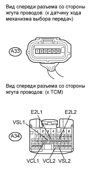
| 8.CHECK HARNESS AND CONNECTOR (SELECT STROKE SENSOR - TCM) |
Disconnect the select stroke sensor connector.
 |
Disconnect the TCM connector.
Measure the resistance according to the value(s) in the table below.
- Standard resistance:
Tester Connection Condition Specified Condition A34-31 (VCL2) - A33-1 Always Below 1 Ω A34-32 (VSL2) - A33-3 ↑ Below 1 Ω A34-24 (E2L2) - A33-2 ↑ Below 1 Ω A34-20 (VCL1) - A33-4 ↑ Below 1 Ω A34-21 (VSL1) - A33-6 ↑ Below 1 Ω A34-22 (E2L1) - A33-5 ↑ Below 1 Ω A34-31 (VCL2) - Body ground ↑ 10 kΩ or higher A34-32 (VSL2) - Body ground ↑ 10 kΩ or higher A34-24 (E2L2) - Body ground ↑ 10 kΩ or higher A34-20 (VCL1) - Body ground ↑ 10 kΩ or higher A34-21 (VSL1) - Body ground ↑ 10 kΩ or higher A34-22 (E2L1) - Body ground ↑ 10 kΩ or higher
Reconnect the select stroke sensor connector.
Reconnect the TCM connector.
|
| ||||
| OK | ||
| ||