READ VALUE OF DIFFERENTIAL PRESSURE
CHECK CONNECTION OF VACUUM HOSE (DIFFERENTIAL PRESSURE SENSOR - VACUUM TRANSMITTING PIPE)
CHECK BLOCKAGE OF VACUUM HOSE AND TRANSMITTING PIPE
CHECK HARNESS AND CONNECTOR (DIFFERENTIAL PRESSURE SENSOR - ECM)
REPLACE DIFFERENTIAL PRESSURE SENSOR ASSEMBLY
CHECK WHETHER DTC OUTPUT RECURS
DTC P1425 Differential Pressure Sensor Circuit |
DTC P1427 Differential Pressure Sensor Circuit Low |
DTC P1428 Differential Pressure Sensor Circuit High |
DESCRIPTION
- УКАЗАНИЕ:
- For more information on the differential pressure sensor and DPF (*1) system: (See page Нажмите здесь).
- If P1425, P1427 and/or P1428 is present, refer to the DTC chart for DPF system (See page Нажмите здесь).
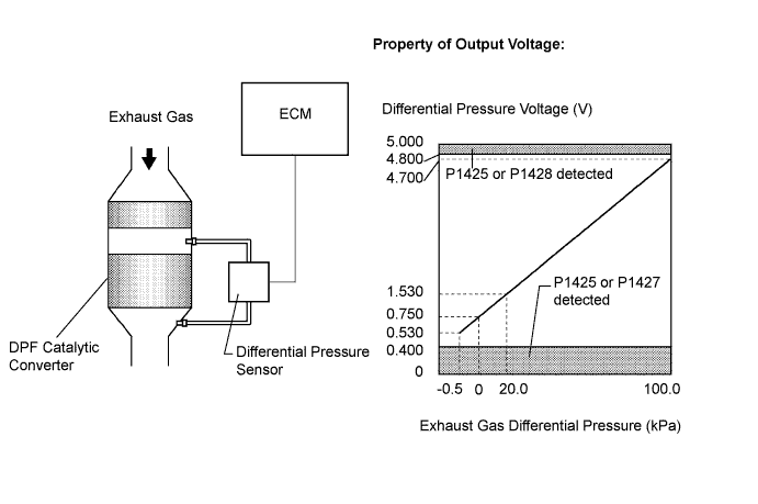
The two sensing chambers of the differential pressure sensor are mounted to monitor the pressure before and after the DPF catalytic converter. The sensor itself is not located on the engine assembly in order to reduce the influence of vibration. The sensor is a semiconductor-type that is not influenced by exhaust gases.
The ECM compares the exhaust gas pressure in front of and behind the DPF catalytic converter by monitoring the pressure using the upstream and downstream sensing chambers of the differential pressure sensor. If the difference between the pressure before and after the catalytic converter exceeds a predetermined level, the ECM judges that the catalytic converter has clogged with particulate matter (PM). When the ECM judges that a partially clogged condition exists, the ECM begins to perform DPF catalyst regeneration.
When the output voltage of the sensor deviates from the normal operating range, the ECM interprets this as a malfunction of the sensor circuit, sets DTC P1425, P1427, or P1428 and illuminates the MIL.
*1: Diesel Particulate Filter
- УКАЗАНИЕ:
- If the vacuum hoses of the differential pressure sensor are incorrectly connected (crossed), the ECM interprets this as abnormal pressure difference, DTC P1426 (Differential Pressure Sensor [Installation]) will be set and the MIL will illuminate.
| DTC No. | DTC Detection Condition | Trouble Area |
| P1425 | Differential pressure sensor output voltage is less than 0.4 V, or more than 4.8 V for 3 seconds or more (1-trip detection logic) |
|
| P1427 | Differential pressure sensor output voltage is less than 0.4 V for 3 seconds or more (1-trip detection logic) | |
| P1428 | Differential pressure sensor output voltage is more than 4.8 V for 3 seconds or more (1-trip detection logic) |
- УКАЗАНИЕ:
- DTC P1426 (Differential pressure sensor [installation]) will be present if there is incorrect vacuum hose routing to the differential pressure sensor.
- After confirming DTCs P1425, P1427 and P1428, check the differential pressure by selecting the following menus on the intelligent tester: "Powertrain / Engine and ECT / Data List / DPNR Differential Pressure".
| Condition | Differential Pressure Output | Sensor Condition |
| Ignition switch on (IG) | Approximately 0 kPa | Normal |
| Always | 3 kPa | Open or short circuit |
| 3000 rpm (No engine load) | Negative output | Incorrect arrangement of hose piping |
MONITOR DESCRIPTION
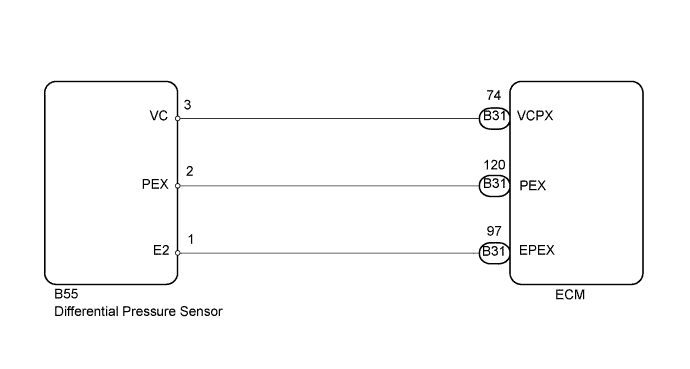
In order to detect abnormality in the differential pressure sensor at any time, the ECM always monitors output voltage from the sensor. When the sensor output voltage deviates from the normal operating range (between 0.4 V and 4.8 V) for more than 3 seconds, the ECM interprets this as a malfunction in the sensor circuit and illuminates the MIL.WIRING DIAGRAM
INSPECTION PROCEDURE
- ПРИМЕЧАНИЕ:
- After replacing the ECM, the new ECM needs registration (See page Нажмите здесь) and initialization (See page Нажмите здесь).
- УКАЗАНИЕ:
- Read freeze frame data using the intelligent tester. The ECM records vehicle and driving condition information as freeze frame data the moment a DTC is stored. When troubleshooting, freeze frame data can help determine if the vehicle was moving or stationary, if the engine was warmed up or not, and other data from the time the malfunction occurred.
| 1.READ VALUE OF DIFFERENTIAL PRESSURE |
Connect the intelligent tester to the DLC3.
Turn the ignition switch on (IG).
Turn the tester on.
Enter the following menu items: Powertrain / Engine and ECT / Data List / DPNR Differential Pressure.
Check that differential pressure is within the specification below.
- Result:
Condition Differential Pressure Proceed to Always -5 kPa or less A Ignition switch on (IG) -4 kPa to 98 kPa B Always 99 kPa C
|
| ||||
|
| ||||
| A | |
| 2.CHECK CONNECTION OF VACUUM HOSE (DIFFERENTIAL PRESSURE SENSOR - VACUUM TRANSMITTING PIPE) |
Check if the vacuum hose routing between the differential pressure sensor and the vacuum transmitting pipe is correct.
Check that there is no exhaust gas leakage between the differential pressure sensor and the vacuum transmitting pipe.
|
| ||||
| OK | |
| 3.CHECK BLOCKAGE OF VACUUM HOSE AND TRANSMITTING PIPE |
- ПРЕДОСТЕРЕЖЕНИЕ:
- Be careful of being burned by exhaust gases during the following inspection.
Disconnect the vacuum hose (both upstream and downstream) on the differential pressure sensor.
Start the engine.
Check if there are exhaust gas pulsations from both vacuum hoses during idling.
|
| ||||
| OK | |
| 4.CHECK HARNESS AND CONNECTOR (DIFFERENTIAL PRESSURE SENSOR - ECM) |
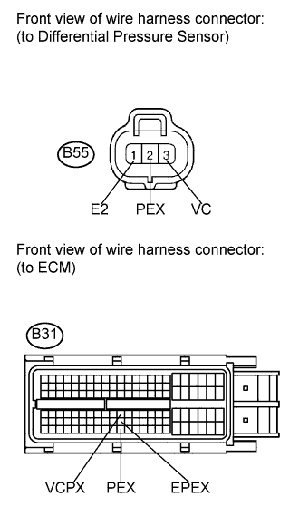
Disconnect the differential pressure sensor connector.
 |
Disconnect the ECM connector.
Measure the resistance according to the value(s) in the table below.
- Standard resistance (Check for open):
Tester Connection Condition Specified Condition B55-2 (PEX) - B31-120 (PEX) Always Below 1 Ω B55-3 (VC) - B31-74 (VCPX) Always Below 1 Ω B55-1 (E2) - B31-97 (EPEX) Always Below 1 Ω
- Standard resistance (Check for short):
Tester Connection Condition Specified Condition B55-2 (PEX) or B31-120 (PEX) - Body ground Always 10 kΩ or higher B55-3 (VC) or B31-74 (VCPX) - Body ground Always 10 kΩ or higher
Reconnect the differential pressure sensor connector.
Reconnect the ECM connector.
|
| ||||
| OK | |
| 5.REPLACE DIFFERENTIAL PRESSURE SENSOR ASSEMBLY |
Replace differential pressure sensor assembly (See page Нажмите здесь).
| NEXT | |
| 6.CHECK WHETHER DTC OUTPUT RECURS |
Connect the intelligent tester to the DLC3.
Turn the ignition switch on (IG) and turn the tester on.
Clear the DTCs (See page Нажмите здесь).
Start the engine and drive the vehicle for approximately 15 minutes.
Enter the following menus: Powertrain / Engine and ECT / DTC.
Read the DTCs.
- Result:
Result Proceed to DTC P1425, P1427 and/or P1428 are output A DTC is not output B
|
| ||||
| A | ||
| ||