CHECK OTHER DTC OUTPUT (IN ADDITION TO DTC P1386)
READ VALUE OF EXHAUST GAS TEMPERATURE
PERFORM ENGINE RPM ACCELERATION (WHITE SMOKE AND FUEL SMELL)
READ VALUE OF EXHAUST GAS TEMPERATURE
INSPECT EXHAUST FUEL ADDITION INJECTOR ASSEMBLY
CHECK HARNESS AND CONNECTOR (EXHAUST FUEL ADDITION INJECTOR ASSEMBLY - ECM)
CHECK HARNESS AND CONNECTOR (EXHAUST FUEL ADDITION INJECTOR ASSEMBLY - EFI MAIN RELAY)
INSPECT FOR FUEL LEAK (IN EXHAUST FUEL ADDITION INJECTOR)
READ VALUE OF INJECTION VOLUME (COMPENSATION OF INJECTION VOLUME)
INSPECT EXHAUST FUEL ADDITION INJECTOR (INJECTION VOLUME)
PERFORM ACTIVE TEST BY INTELLIGENT TESTER (DPF CATALYST REGENERATION)
REPLACE EXHAUST FUEL ADDITION INJECTOR ASSEMBLY
PERFORM ACTIVE TEST BY INTELLIGENT TESTER (DPF CATALYST REGENERATION)
INSPECT EXHAUST FUEL ADDITION INJECTOR (INJECTION VOLUME)
DTC P1386 Injector for Exhaust Fuel Addition |
DESCRIPTION
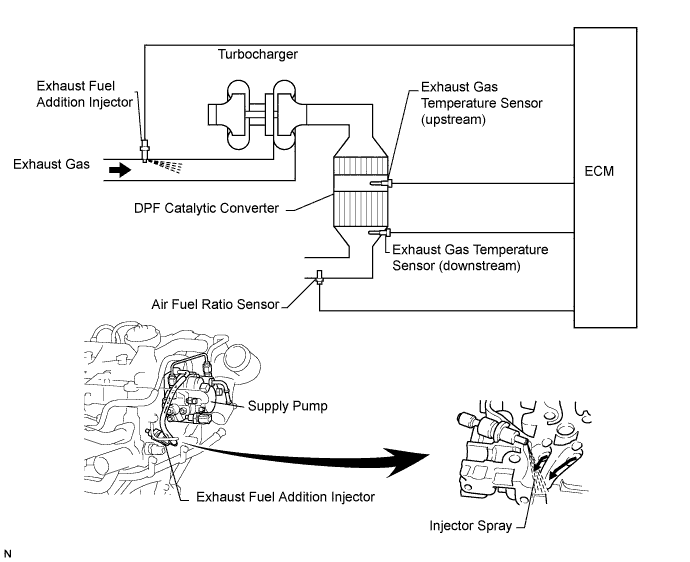
The exhaust fuel addition injector is mounted on the exhaust port of the cylinder head, and low pressure is provided to the injector by the feed pump in the supply pump. This injector adds fuel by a control signal from the ECM.
This injector is used for DPF (*1) catalyst regeneration.
Under the DPF catalyst regeneration control, the injector adds fuel to raise a catalyst temperature.
- УКАЗАНИЕ:
- For more information on the exhaust fuel addition injector and DPF system: (See page Нажмите здесь)
- If P1386 is present, refer to the diagnostic trouble code (DTC) chart for DPF system (See page Нажмите здесь).
- "Learning value" used in here represents a correction learning value of the fuel addition volume to raise the DPF catalyst temperature to a target range.
- *1: Diesel Particulate Filter
| DTC No. | DTC Detection Condition | Main Trouble Area | Related Trouble Area |
| P1386 | Low fuel addition volume from exhaust fuel addition injector: Learning value (*3) exceeds standard level (1-trip detection logic) |
|
|
| Exhaust fuel addition injector nozzle stuck open: Air-fuel ratio becomes RICHER than standard level, or exhaust gas temperature becomes higher than standard level (1-trip detection logic) |
- УКАЗАНИЕ:
- DTC P2047, P2048 or P2049 will be present if there is an open in the exhaust fuel addition injector circuit.
- If any one of the main injectors has a closed valve malfunction, rough idle will result. Compensatory injection volume learning values of each cylinder can be read by using the intelligent tester. When the value is more than 3.5 mm3, the cylinder is malfunctioning.
- Usually compensation injection volume is 3.5 mm3 or less.
MONITOR DESCRIPTION
- УКАЗАНИЕ:
- "Learning value" used here represents a correction learning value of the fuel addition volume to raise the DPF (*4) catalyst temperature to a target range.
- *4: Diesel Particulate Filter
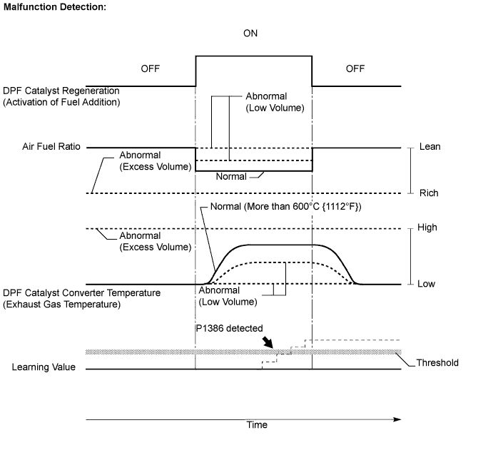
- The ECM always monitors the DPF catalytic converter temperature and the air-fuel ratio. When the temperature becomes higher than its usual level or the air-fuel ratio becomes extremely RICH, the ECM judges that the injector has stuck open and illuminates the MIL. If this malfunction occurs, the ECM enters the fail-safe mode to limit the acceptable vehicle speed to approximately 80 km/h (50 mph) at maximum by limiting the engine power.
- During DPF catalyst regeneration, the ECM monitors the learning value. Normally, the learning value for the DPF catalyst regeneration is in the vicinity of 1.0. Thus if the learning value is at 1.99 or more for a certain period of time, the ECM judges the fuel addition volume from the injector is insufficient and illuminates the MIL. If this malfunction occurs, the ECM enters the fail-safe mode to limit the acceptable vehicle speed to approximately 80 km/h (50 mph) at maximum by limiting the engine power.
| Fail-Safe Operation | Malfunction Condition | Malfunction Detection Condition | Drive Pattern |
Limits engine power by permitting driving at a maximum vehicle speed of approximately 80 km/h (50 mph)
| Exhaust fuel addition injector has stuck open | DPF catalytic converter temperature becomes higher than 800°C (1472°F) or air-fuel ratio is less than approximately 12.0: 1 for a couple of seconds | Idling engine for more than 5 minutes (*5) |
| Low fuel addition volume from the exhaust fuel addition injector | During DPF catalyst regeneration, when learning value of 1.99 or more continues for a certain period of time (*6) | After warming up the engine, perform DPF REJU (PM) in the ACTIVE TEST menu using the intelligent tester, and drive at constant vehicle speed within 50 to 100 km/h (31 to 62 mph) for more than 30 minutes |
*6: While the DPF catalyst regeneration is performed, the ECM raises the DPF catalytic converter temperature to more than 600°C (1112°F) by adding fuel using the exhaust fuel addition injector. If the temperature does not reach 600°C (1112 °F) during the attempt, the correction learning value of the fuel addition volume increases by increments in order to raise the DPF catalytic converter temperature to the target range.
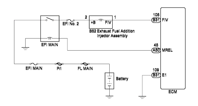
WIRING DIAGRAM
INSPECTION PROCEDURE
- УКАЗАНИЕ:
- "Learning value" used in here represents a correction learning value of the fuel addition volume to raise the DPF catalyst temperature to a target range.
- Read freeze frame data using the intelligent tester. The ECM records vehicle and driving condition information as freeze frame data the moment a DTC is stored. When troubleshooting, freeze frame data can help determine if the vehicle was moving or stationary, if the engine was warmed up or not, and other data from the time the malfunction occurred.
| 1.CHECK OTHER DTC OUTPUT (IN ADDITION TO DTC P1386) |
Connect the intelligent tester to the DLC3.
Turn the ignition switch on (IG).
Turn the tester on.
Enter the following menu items: Powertrain / Engine and ECT / DTC.
Read the DTCs.
- Result:
Result Proceed to DTC P1386 is output A DTC P1386 and other DTCs are output B
- УКАЗАНИЕ:
- If codes other than P1386 are output, perform troubleshooting for those DTCs first.
|
| ||||
| A | |
| 2.READ VALUE OF EXHAUST GAS TEMPERATURE |
Connect the intelligent tester to the DLC3.
Turn the ignition switch on (IG). (Do not start the engine.)
Turn the tester on.
Enter the following menu items: Powertrain / Engine and ECT / Data List / Initial Exhaust Temp (In) and Initial Exhaust Temp (Out).
Read the value.
- Result:
Result Proceed to Temperature displayed: OK (Same value as actual exhaust gas temperature) A Temperature displayed: 1000°C (1832°F) B
- УКАЗАНИЕ:
- If there is an open circuit, the intelligent tester indicates 1000°C (1832°F).
|
| ||||
| A | |
| 3.PERFORM ENGINE RPM ACCELERATION (WHITE SMOKE AND FUEL SMELL) |
- ПРЕДОСТЕРЕЖЕНИЕ:
- Stop the engine immediately if there is white smoke or a fuel smell during the inspection below. Fuel may be leaking from the exhaust fuel addition injector.
Disconnect the battery cable for 1 minute, and then reconnect the cable.
After the engine starts, promptly accelerate the engine to approximately 3000 rpm with no load 3 times.
Check for white smoke in exhaust gases.
Check for a fuel smell in exhaust gases.
- Result:
Result Proceed to Either white smoke or fuel smells in exhaust gases A Other than above B
|
| ||||
| B | |
| 4.READ VALUE OF AIR FUEL RATIO |
- ПРЕДОСТЕРЕЖЕНИЕ:
- Stop the engine immediately if there is white smoke or a fuel smell during the inspection below. Fuel may be leaking from the exhaust fuel addition injector.
Connect the intelligent tester to the DLC3.
Turn the ignition switch on (IG).
Turn the tester on.
Start the engine.
Enter the following menu items: Powertrain / Engine and ECT / Data List / AFS B1 S1.
Read the air fuel ratio displayed on the tester after idling the engine for 3 minutes.
- Result:
Result Proceed to Air fuel ratio: More than 12 A Air fuel ratio: Less than 12 B
|
| ||||
| A | |
| 5.READ VALUE OF EXHAUST GAS TEMPERATURE |
- ПРЕДОСТЕРЕЖЕНИЕ:
- Stop the engine immediately if there is white smoke or a fuel smell during the inspection below. Fuel may be leaking from the exhaust fuel addition injector.
Connect the intelligent tester to the DLC3.
Turn the ignition switch on (IG).
Turn the tester on.
Start the engine.
Enter the following menu items: Powertrain / Engine and ECT / Data List / Initial Exhaust Temp (In) and Initial Exhaust Temp (Out).
Check that exhaust gas temperature is within the specification below.
- Result:
Result Exhaust Gas Temperature (°C) Idling after warming up engine Constant at approximately 50 to 700°C (122 to 1292°F)
|
| ||||
| OK | |
| 6.READ VALUE OF AIR FUEL RATIO |
Connect the intelligent tester to the DLC3.
Turn the ignition switch on (IG).
Turn the tester on.
Start the engine.
Enter the following menu items: Powertrain / Engine and ECT / Data List / AFS B1 S1.
After warming up the engine, check if the air-fuel ratio varies when accelerating the engine from idling to 3000 rpm by fully depressing the accelerator pedal 3 times.
- Result:
Result Proceed to Air fuel ratio: Varies OK Air fuel ratio: Does not vary once NG
|
| ||||
| OK | |
| 7.INSPECT EXHAUST FUEL ADDITION INJECTOR ASSEMBLY |
Disconnect the exhaust fuel addition injector connector.
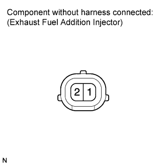 |
Measure the resistance according to the value(s) in the table below.
- Standard resistance:
Tester Connection Condition Specified Condition 1 - 2 20°C (68°F) 7.1 to 7.9 Ω
Reconnect the exhaust fuel addition injector connector.
|
| ||||
| OK | |
| 8.CHECK FUSE (EFI NO. 2 FUSE) |
Remove the EFI No. 2 fuse from the engine room relay block.
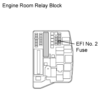 |
Measure the resistance according to the value(s) in the table below.
- Standard resistance:
Tester Connection Condition Specified Condition EFI No. 2 fuse Always Below 1 Ω
Reinstall the EFI No. 2 fuse.
|
| ||||
| OK | |
| 9.CHECK HARNESS AND CONNECTOR (EXHAUST FUEL ADDITION INJECTOR ASSEMBLY - ECM) |
Disconnect the exhaust fuel addition injector assembly connector.
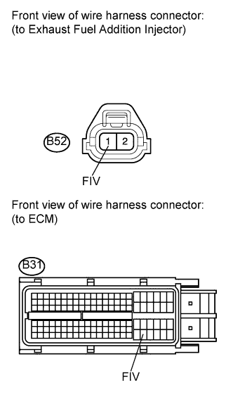 |
Disconnect the ECM connector.
Measure the resistance according to the value(s) in the table below.
- Standard resistance (Check for open):
Tester Connection Condition Specified Condition B52-1 (FIV) - B31-105 (FIV) Always Below 1 Ω
- Standard resistance (Check for short):
Tester Connection Condition Specified Condition B52-1 (FIV) or B31-105 (FIV) - Body ground Always 10 kΩ or higher
Reconnect the exhaust fuel addition injector assembly connector.
Reconnect the ECM connector.
|
| ||||
| OK | |
| 10.CHECK HARNESS AND CONNECTOR (EXHAUST FUEL ADDITION INJECTOR ASSEMBLY - EFI MAIN RELAY) |
Disconnect the exhaust fuel addition injector assembly connector.
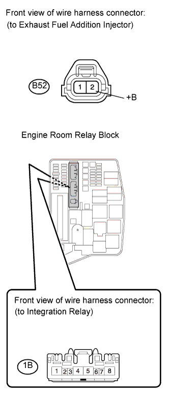 |
Remove the integration relay from the engine room relay block.
Disconnect the integration relay connector.
Measure the resistance according to the value(s) in the table below.
- Standard resistance (Check for open):
Tester Connection Condition Specified Condition B52-2 (+B) - 1B-4 Always Below 1 Ω
- Standard resistance (Check for short):
Tester Connection Condition Specified Condition B52-2 (+B) or 1B-4 - Body ground Always 10 kΩ or higher
Reconnect the exhaust fuel addition injector connector.
Reconnect the integration relay connector.
Reinstall the integration relay.
|
| ||||
| OK | |
| 11.INSPECT FOR FUEL LEAK (IN EXHAUST FUEL ADDITION INJECTOR) |
Visually check if there is a fuel leak between the supply pump and exhaust fuel addition injector.
- OK:
- There is no fuel leak.
- УКАЗАНИЕ:
- Primary pressure of maximum 1 MPa (10 kgf/cm2, 145 psi) is provided from a feed pump inside the supply pump to the exhaust fuel addition injector.
- Fuel leaks are possible inside the components (supply pump, etc).
|
| ||||
| OK | |
| 12.READ VALUE OF INJECTION VOLUME (COMPENSATION OF INJECTION VOLUME) |
Connect the intelligent tester to the DLC3.
Turn the ignition switch on (IG).
Turn the tester on.
Start the engine.
Enter the following menu items: Powertrain / Engine and ECT / Data List / Injection Feedback Value.
Read the value.
- Result:
Result Proceed to Compensatory injection volume is more than 3.0 mm3 (0.18 cu.in.) A Compensatory injection volume is 3.0 mm3 (0.18 cu.in.) or less B
- УКАЗАНИЕ:
- Usually compensation injection volume is 3.0 mm3 (0.18 cu.in.) or less.
|
| ||||
| A | |
| 13.CHECK ENGINE COMPONENT PARTS |
Check that there is no abnormality in the main injector, cylinder compression pressure, valve timing, and valve clearance.
Check that there is no leakage or blockage in the air intake, exhaust, and EGR systems.
- OK:
- No abnormality in the component parts.
|
| ||||
| OK | |
| 14.INSPECT EXHAUST FUEL ADDITION INJECTOR (INJECTION VOLUME) |
Remove the exhaust fuel addition injector.
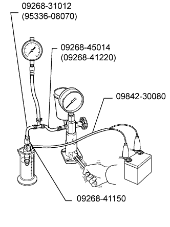 |
Attach the exhaust fuel addition injector to a nozzle tester.
- SST
- 09268-31012(95336-08070)
09268-45014(09268-41220)
09268-41150
Apply a pressure of 0.29 MPa (3.0 kgf/cm2, 42 psi) to the nozzle tester.
Connect SST (wire) to the exhaust fuel addition injector.
- SST
- 09842-30080
Inspect the injector.
- Standard:
Condition Result Leave the injector undisturbed for 1 minute with fuel pressurized No leakage from the injector Apply battery voltage to the injector Fuel is emitted from the injector
- УКАЗАНИЕ:
- Injection volume after leaving the exhaust fuel addition injector for 10 seconds with the pressurized fuel applied is as follows:
- Reference:
- 25 cm3 (1.5 cu.in.)
- The above is a reference value, thus, your reading may differ from this value depending on the measuring conditions, etc.
- Check that the nozzle of the exhaust fuel addition injector is not clogged.
Reinstall the exhaust fuel addition injector.
|
| ||||
| OK | |
| 15.PERFORM ACTIVE TEST BY INTELLIGENT TESTER (DPF CATALYST REGENERATION) |
Clear the learning value by removing the negative battery cable for more than 1 minute.
Connect the intelligent tester to the DLC3.
Turn the ignition switch on (IG).
Turn the tester on.
Enter the following menu items: Powertrain / Engine and ECT / Active Test / Activate the DPNR Rejuvenate (PM).
After warming up the engine, drive the vehicle at a constant speed between 50 and 100 km/h (31 and 62 mph) (with smooth throttle operations) for more than 15 minutes.
Enter the following menus: "Powertrain / Engine and ECT / Data List / AFS B1 S1, Initial Exhaust Temp (In), Initial Exhaust Temp (Out) and Exhaust Fuel Addition FB".
Check the exhaust gas temperatures (Initial Exhaust Temp (In) and (Out)) and the learning value (Exhaust Fuel Addition FB).
- Result:
Result Proceed to Exhaust gas temperature does not become higher than 600°C (1112°F) A Exhaust gas temperature becomes higher than 600°C (1112°F), and the learning value remains in the vicinity of 1.0 B
|
| ||||
| A | |
| 16.REPLACE EXHAUST FUEL ADDITION INJECTOR ASSEMBLY |
Replace the exhaust fuel addition injector assembly (See page Нажмите здесь).
| NEXT | |
| 17.PERFORM ACTIVE TEST BY INTELLIGENT TESTER (DPF CATALYST REGENERATION) |
Clear the learning value by removing the negative battery cable for more than 1 minute.
Connect the intelligent tester to the DLC3.
Turn the ignition switch on (IG).
Turn the tester on.
Enter the following menu items: Powertrain / Engine and ECT / Active Test / Activate the DPNR Rejuvenate (PM).
After warming up the engine, drive the vehicle at a constant speed between 50 and 100 km/h (31 and 62 mph) (with smooth throttle operations) for more than 15 minutes.
Enter the following menu items: Powertrain / Engine and ECT / Data List / AFS B1 S1, Initial Exhaust Temp (In), Initial Exhaust Temp (Out) and Exhaust Fuel Addition FB.
Check the exhaust gas temperatures (Initial Exhaust Temp (In) and (Out)) and the learning value (Exhaust Fuel Addition FB).
- Result:
Result Proceed to Exhaust gas temperature does not become higher than 600°C (1112°F) A Exhaust gas temperature becomes higher than 600°C (1112°F), and the learning value remains in the vicinity of 1.0 B
|
| ||||
| A | ||
| ||
| 18.INSPECT EXHAUST FUEL ADDITION INJECTOR (INJECTION VOLUME) |
Remove the exhaust fuel addition injector.
|
Attach the exhaust fuel addition injector to a nozzle tester.
- SST
- 09268-31012(95336-08070)
09268-45014(09268-41220)
09268-41150
Apply a pressure of 0.29 MPa (3.0 kgf/cm2, 42 psi) to the nozzle tester.
Connect SST (Wire) to the exhaust fuel addition injector.
- SST
- 09842-30080
Inspect the injector.
- Standard:
Condition Result Leave the injector undisturbed for 1 minute with fuel pressurized No leakage from the injector Apply battery voltage to the injector Fuel is emitted from the injector
- УКАЗАНИЕ:
- Injection volume after leaving the exhaust fuel addition injector for 10 seconds with the pressurized fuel applied as follows:
- Reference:
- 25 cm3 (1.5 cu.in.)
- The above is a reference value, thus, your reading may differ from this value depending on the measuring conditions, etc.
- Check that the nozzle of the exhaust fuel addition injector is not clogged.
Reinstall the exhaust fuel addition injector.
|
| ||||
| OK | ||
| ||