READ VALUE OF EXHAUST GAS TEMPERATURE SENSOR
CHECK HARNESS AND CONNECTOR (OPEN IN WIRE HARNESS)
CHECK HARNESS AND CONNECTOR (EXHAUST GAS TEMPERATURE SENSOR - ECM)
READ VALUE OF HARNESS AND CONNECTOR (SHORT IN WIRE HARNESS)
CHECK HARNESS AND CONNECTOR (EXHAUST GAS TEMPERATURE SENSOR - ECM)
DTC P0544 Exhaust GAS Temperature Sensor Circuit (Bank 1 Sensor 1) |
DTC P0545 Exhaust Gas Temperature Sensor Circuit Low (Bank 1 Sensor 1) |
DTC P0546 Exhaust Gas Temperature Sensor Circuit High (Bank 1 Sensor 1) |
DTC P2031 Exhaust Gas Temperature Sensor Circuit (Bank 1 Sensor 2) |
DTC P2032 Exhaust Gas Temperature Sensor Circuit Low (Bank 1 Sensor 2) |
DTC P2033 Exhaust Gas Temperature Sensor Circuit High (Bank 1 Sensor 2) |
DESCRIPTION
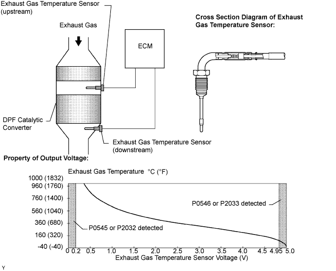
The exhaust gas temperature sensors are installed in front of and behind the DPF (*1) catalytic converter to sense the exhaust gas temperature.
A thermistor built into the sensor changes its resistance value according to the exhaust gas temperature. The lower the exhaust gas temperature, the greater the thermistor resistance value. The greater the exhaust gas temperature, the lower the thermistor resistance value.
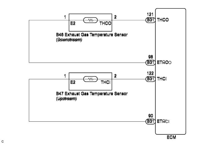
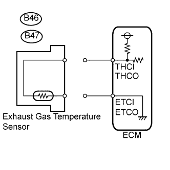
The exhaust gas temperature sensor is connected to the ECM. The 5 V power source voltage in the ECM is applied to the exhaust gas temperature sensor from terminals THCI (upstream) and THCO (downstream) via resistor R.
The resistor R and the exhaust gas temperature sensor are connected in series. When the resistance value of the exhaust gas temperature sensor changes in accordance with changes in the exhaust gas temperature, the voltage at terminals THCI (upstream) and THCO (downstream) also changes. Based on these signals, when DPF catalyst regeneration is needed, the ECM operates the exhaust fuel addition injector to obtain target upstream temperature of the DPF catalytic converter as mentioned through sensor 1. In addition, the ECM monitors the rate of DPF catalytic converter temperature increase using sensor 2.
*1: Diesel Particulate Filter.
| DTC No. | DTC Detection Condition | Trouble Area |
| P0544 | Sensor 1 output is less than 0.2 V or more than 4.95 V for 3 seconds or more (1-trip detection logic) |
|
| P0545 | Sensor 1 output is less than 0.2 V for 3 seconds or more (1-trip detection logic) | |
| P0546 | Sensor 1 output is more than 4.95 V for 3 seconds or more (1-trip detection logic) | |
| P2031 | Sensor 2 output is less than 0.2 V or more than 4.95 V for 3 seconds or more (1-trip detection logic) |
|
| P2032 | Sensor 2 output is less than 0.2 V for 3 seconds or more (1-trip detection logic) | |
| P2033 | Sensor 2 output is more than 4.95 V for 3 seconds or more (1-trip detection logic) |
- УКАЗАНИЕ:
- DTC P1386 (Exhaust fuel addition injector malfunction) will be present if there is an open in an exhaust gas temperature sensor circuit.
- Sensor 1 represents a sensor located upstream on the DPF catalytic converter.
- Sensor 2 represents a sensor located downstream on the DPF catalytic converter.
- After confirming DTCs P0544, P0545, P0546, P2031, P2032, and P2033, check the upstream and downstream exhaust gas temperature by selecting the following menus on the intelligent tester: "Powertrain / Engine and ECT / Data List / Initial Exhaust Temp (In) and Initial Exhaust Temp (Out)".
| Condition | Exhaust Gas Temperature | Exhaust Gas Temperature Sensor Condition |
| Idling after warm-up | Constant at 50 to 700°C (122 to 1292°F) | Normal |
| 0°C (32°F) | Short circuit | |
| 1000°C (1832°F) | Open circuit |
MONITOR DESCRIPTION
The ECM constantly monitors the output voltages from the sensors in order to detect problems with the sensors. When the sensor output voltage deviates from the normal operating range (between 0.2 V and 4.95 V) for more than 3 seconds after the engine is warmed up, the ECM interprets this as a malfunction of the sensor circuit, and illuminates the MIL.WIRING DIAGRAM
INSPECTION PROCEDURE
- ПРИМЕЧАНИЕ:
- After replacing the ECM, the new ECM needs registration (See page Нажмите здесь) and initialization (See page Нажмите здесь).
- УКАЗАНИЕ:
- Read freeze frame data using the intelligent tester. The ECM records vehicle and driving condition information as freeze frame data the moment a DTC is stored. When troubleshooting, freeze frame data can help determine if the vehicle was moving or stationary, if the engine was warmed up or not, and other data from the time the malfunction occurred.
| 1.READ VALUE OF EXHAUST GAS TEMPERATURE SENSOR |
Connect the intelligent tester to the DLC3.
Turn the ignition switch on (IG).
Turn the tester on.
Enter the following menu items: Powertrain / Engine and ECT / Data List / Initial Exhaust Temp (In) and Initial Exhaust Temp (Out).
Read the value.
- Standard:
- Same as the actual exhaust gas temperature (50 to 700°C [122 to 1292°F] during idling after warm-up), and varies after an engine speed of 3000 rpm is maintained for 1 minute.
- Result:
Temperature Displayed Proceed to 1000°C (1832°F) A 0°C (32°F) (After warming up the engine) B OK: Same as the actual exhaust gas temperature (50 to 700°C [122 to 1292°F] during idling after warm-up), and varies after maintaining the engine speed of 3000 rpm for 1 minute after accelerating the engine from idling to 3000 rpm C
- УКАЗАНИЕ:
- If there is a short circuit, the intelligent tester will indicate 0°C (32°F).
- If there is an open circuit, the intelligent tester will indicate 1000°C (1832°F).
|
| ||||
|
| ||||
| A | |
| 2.CHECK HARNESS AND CONNECTOR (OPEN IN WIRE HARNESS) |
Disconnect the exhaust gas temperature sensor connector.
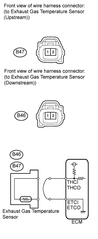 |
Connect terminals 1 and 2 of the exhaust gas temperature sensor wire harness side connector.
Connect the intelligent tester to the DLC 3.
Turn the ignition switch on (IG).
Turn the tester on.
Enter the following menu items: Powertrain / Engine and ECT / Data List / Initial Exhaust Temp (In) and Initial Exhaust Temp (Out).
Read the value.
- Standard:
- 0°C (32°F)
Reconnect the exhaust gas temperature sensor connector.
|
| ||||
| OK | ||
| ||
| 3.CHECK HARNESS AND CONNECTOR (EXHAUST GAS TEMPERATURE SENSOR - ECM) |
Disconnect the exhaust gas temperature sensor connector.
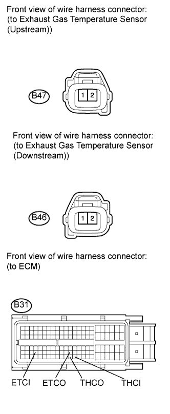 |
Disconnect the ECM connector.
Measure the resistance according to the value(s) in the table below.
- Standard resistance:
Tester Connection Condition Specified Condition B46-2 (THCO) - B31-121 (THCO) Always Below 1 Ω B46-1 (E2) - B31-98 (ETCO) Always Below 1 Ω B47-2 (THCI) - B31-122 (THCI) Always Below 1 Ω B47-1 (E2) - B31-90 (ETCI) Always Below 1 Ω
Reconnect the exhaust gas temperature sensor connector.
Reconnect the ECM connector.
|
| ||||
| OK | ||
| ||
| 4.READ VALUE OF HARNESS AND CONNECTOR (SHORT IN WIRE HARNESS) |
Disconnect the exhaust gas temperature sensor connector.
 |
Connect the intelligent tester to the DLC3.
Turn the ignition switch on (IG).
Turn the tester on.
Enter the following menu items: Powertrain / Engine and ECT / Data List / Initial Exhaust Temp (In) and Initial Exhaust Temp (Out).
Read the value(s).
- Standard:
- 1000°C (1832°F)
Reconnect the exhaust gas temperature sensor connector.
|
| ||||
| OK | ||
| ||
| 5.CHECK HARNESS AND CONNECTOR (EXHAUST GAS TEMPERATURE SENSOR - ECM) |
Disconnect the exhaust gas temperature sensor connector.
|
Disconnect the ECM connector.
Measure the resistance according to the value(s) in the table below.
- Standard resistance:
Tester Connection Condition Specified Condition B46-2 (THCO) or B31-121 (THCO) - Body ground Always 10 kΩ or higher B46-1 (E2) or B31-98 (ETCO) - Body ground Always 10 kΩ or higher B47-2 (THCI) or B31-122 (THCI) - Body ground Always 10 kΩ or higher B47-1 (E2) or B31-90 (ETCI) - Body ground Always 10 kΩ or higher
Reconnect the exhaust gas temperature sensor connector.
Reconnect the ECM connector.
|
| ||||
| OK | ||
| ||