CHECK OTHER DTC OUTPUT (IN ADDITION TO DTC P0400)
READ VALUE OF INTELLIGENT TESTER (EGR POSITION)
INSPECT EGR VALVE ASSEMBLY (EGR VALVE POSITION SENSOR RESISTANCE)
CHECK HARNESS AND CONNECTOR (EGR VALVE ASSEMBLY - ECM)
CHECK HARNESS AND CONNECTOR (EGR VALVE ASSEMBLY - EFI MAIN RELAY)
CHECK WHETHER DTC OUTPUT RECURS
DTC P0400 Exhaust Gas Recirculation Flow |
DESCRIPTION
The EGR system recirculates exhaust gases, in order to suit every driving condition. The recirculated gas mingles with the intake air, therefore the EGR system can slow combustion speed and keep the combustion temperature down. This helps reduce NOx emissions.In order to increase EGR circulation efficiency, the ECM adjusts the lift amount of the EGR valve and intake shutter valve angle (throttle valve).
| DTC No. | DTC Detection Condition | Trouble Area |
| P0400 | When either condition below is met:
|
|
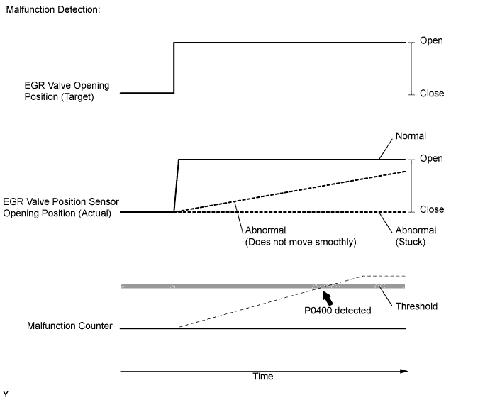
MONITOR DESCRIPTION
- If the EGR valve is forcibly operated but the intake air amount does not vary, the ECM determines that the EGR valve is malfunctioning. The ECM then illuminates the MIL.
- When the target and actual positions of the EGR valve are different, the ECM interprets this as a malfunction of the EGR valve and illuminates the MIL.
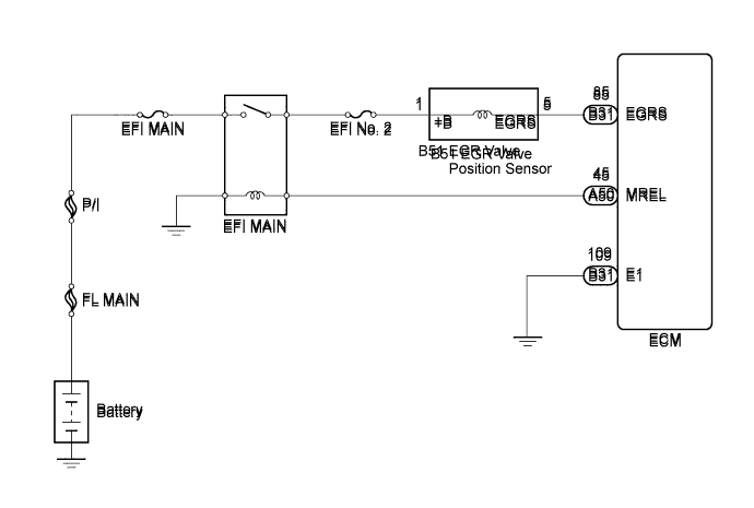
WIRING DIAGRAM
INSPECTION PROCEDURE
- ПРИМЕЧАНИЕ:
- After replacing the ECM, the new ECM needs registration (See page Нажмите здесь) and initialization (See page Нажмите здесь).
- УКАЗАНИЕ:
- After warming up the engine, DTC P0400 can be set if 1 second or more passes after quickly accelerating the engine from idling.
- Read freeze frame data using the intelligent tester. The ECM records vehicle and driving condition information as freeze frame data the moment a DTC is stored. When troubleshooting, freeze frame data can help determine if the vehicle was moving or stationary, if the engine was warmed up or not, and other data from the time the malfunction occurred.
| 1.CHECK OTHER DTC OUTPUT (IN ADDITION TO DTC P0400) |
Connect the intelligent tester to the DLC3.
Turn the ignition switch on (IG) and turn the tester on.
Enter the following menus: Powertrain / Engine and ECT / DTC.
Read the DTCs.
- Result:
Result Proceed to DTC P0400 is output A DTC P0400 and P0405 and/or P0406 are output B
- УКАЗАНИЕ:
- If codes other than P0400 are output, perform troubleshooting for those DTCs first.
|
| ||||
| A | |
| 2.READ VALUE OF INTELLIGENT TESTER (EGR POSITION) |
Connect the intelligent tester to the DLC3.
Turn the ignition switch on (IG) and turn the tester on.
Enter the following menus: Powertrain / Engine and ECT / Data List / EGR Position.
Read the value.
- Result:
Condition Result Proceed to After warming up the engine, quickly accelerate the engine from idling to 3000 rpm by using the accelerator pedal Constant or changes slowly A Smooth changes from approximately 0% to approximately 50% B
- УКАЗАНИЕ:
- EGR valve closed: EGR position is 0%
- EGR valve open: EGR position is 65%
|
| ||||
| A | |
| 3.INSPECT EGR VALVE ASSEMBLY (EGR VALVE POSITION SENSOR RESISTANCE) |
Disconnect the EGR valve position sensor connector.
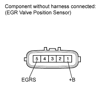 |
Measure the resistance according to the value(s) in the table below.
- Standard resistance:
Tester Connection Condition Specified Condition 5 (EGRS) - 1 (+B) 20°C (68°F) Approximately 6.5 to 7.5 Ω
Reconnect the EGR valve position sensor connector.
|
| ||||
| OK | |
| 4.CHECK HARNESS AND CONNECTOR (EGR VALVE ASSEMBLY - ECM) |
Disconnect the EGR valve position sensor connector.
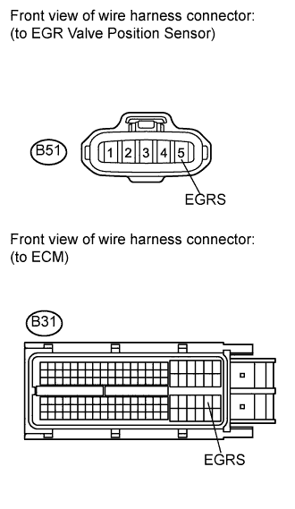 |
Disconnect the ECM connector.
Measure the resistance according to the value(s) in the table below.
- Standard resistance (Check for open):
Tester Connection Condition Specified Condition B51-5 (EGRS) - B31-85 (EGRS) Always Below 1 Ω
- Standard resistance (Check for short):
Tester Connection Condition Specified Condition B51-5 (EGRS) or B31-85 (EGRS) - Body ground Always 10 kΩ or higher
Reconnect the EGR valve position sensor connector.
Reconnect the ECM connector.
|
| ||||
| OK | |
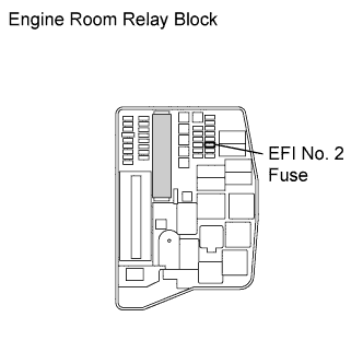
| 5.CHECK HARNESS AND CONNECTOR (EGR VALVE ASSEMBLY - EFI MAIN RELAY) |
Inspect the EFI No. 2 fuse.
Remove the EFI No. 2 fuse from the engine room relay block.
Measure the resistance according to the value(s) in the table below.
- Standard resistance:
Tester Connection Condition Specified Condition EFI No. 2 fuse Always Below 1 Ω
Reinstall the EFI No. 2 fuse.
 |
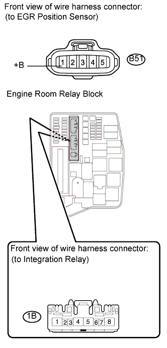
Check the wire harness between the EGR valve position sensor and EFI MAIN relay.
Disconnect the EGR valve position sensor connector.
Remove the integration relay from the engine room relay block.
Disconnect the integration relay connector.
Measure the resistance according to the value(s) in the table below.
- Standard resistance (Check for open):
Tester Connection Condition Specified Condition B51-1 (+B) - 1B-4 Always Below 1 Ω
- Standard resistance (Check for short):
Tester Connection Condition Specified Condition B51-1 (+B) or 1B-4 - Body ground Always 10 kΩ or higher
Reconnect the EGR valve position sensor connector.
Reconnect the integration relay connector.
Reinstall the integration relay.
 |
|
| ||||
| OK | |
| 6.REPLACE EGR VALVE ASSEMBLY |
Replace the EGR valve position sensor (See page Нажмите здесь).
| NEXT | |
| 7.CHECK WHETHER DTC OUTPUT RECURS |
Connect the intelligent tester to the DLC3.
Turn the ignition switch on (IG) and turn the tester on.
Clear the DTCs (See page Нажмите здесь).
Start the engine and drive the vehicle for approximately 15 minutes.
Enter the following menus: Powertrain / Engine and ECT / DTC.
Read the DTCs.
- Result:
Result Proceed to DTC P0400 is output A DTC is not output B
|
| ||||
| A | ||
| ||