Двигатель. COROLLA, AURIS. ZZE150 ZRE151,152 NDE150
DESCRIPTION
MONITOR DESCRIPTION
MONITOR STRATEGY
TYPICAL ENABLING CONDITIONS
TYPICAL MALFUNCTION THRESHOLDS
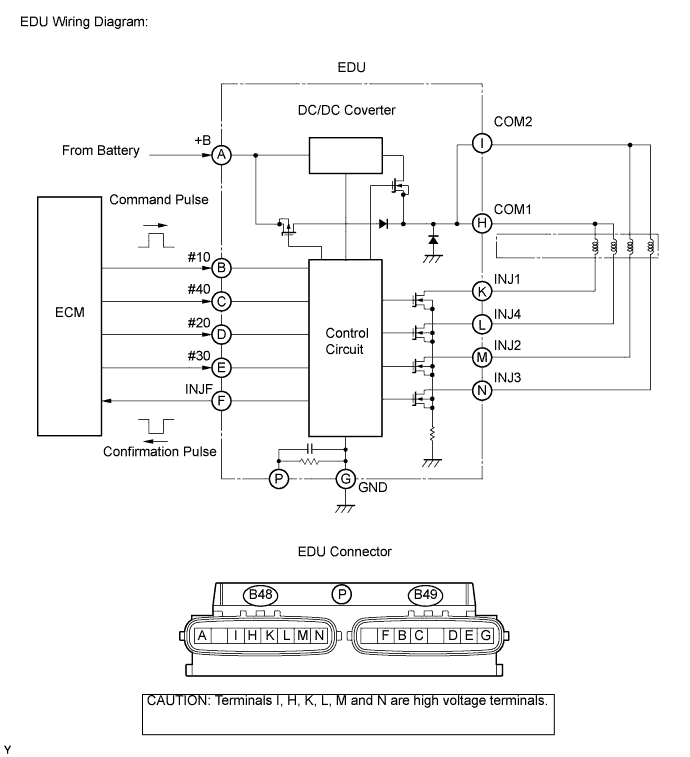
WIRING DIAGRAM
INSPECTION PROCEDURE
INSPECT INJECTOR ASSEMBLY
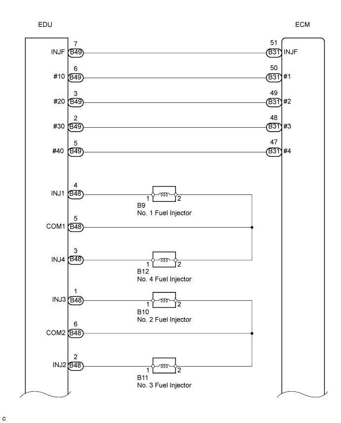
CHECK HARNESS AND CONNECTOR (INJECTOR - EDU)
CHECK HARNESS AND CONNECTOR (EDU - ECM)
CHECK TERMINAL VOLTAGE EDU POWER SOURCE
REPLACE EDU
CHECK WHETHER DTC OUTPUT RECURS
CHECK HARNESS AND CONNECTOR (EDU - BODY GROUND)
CHECK FUSE (EDU FUSE)
INSPECT INTEGRATION RELAY (EDU RELAY)
INSPECT ECM (IREL VOLTAGE)
CHECK HARNESS AND CONNECTOR (EDU - EDU RELAY)
CHECK FUSE (EFI NO. 1 FUSE)
CHECK HARNESS AND CONNECTOR (ECM - EDU RELAY)
DTC P0200 Injector Circuit / Open |
DESCRIPTION
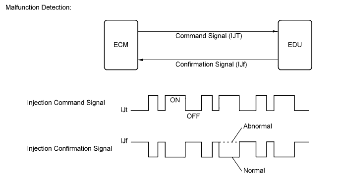
The EDU drives the injectors at high speeds. The EDU delivers high-speed drive signals under high-pressure fuel conditions using the DC/DC converter, which provides a high-voltage and quick-charging system.Soon after the EDU receives an injection command (#) signal from the ECM, the EDU responds to the command with an injector injection confirmation (INJF) signal when the current is applied to the injector.DTC No.
| DTC Detection Condition
| Trouble Area
|
P0200
| Open or short in EDU or injector circuit
After engine is started, there is no INJF signal from EDU to ECM, despite ECM sending # signals to EDU
(1-trip detection logic)
| - Open or short in EDU circuit
- Injector
- EDU
- ECM
|
- УКАЗАНИЕ:
- DTC P0200 is detected when starting the engine and letting it idle for 30 seconds.
MONITOR DESCRIPTION
- P0200 (Open or short in EDU or injector circuit):
The ECM continuously monitors both injection command (#) signals and injection confirmation (INJF) signals. This DTC will be set if the ECM determines that the number of # signals and INJF signals are inconsistent.
The injectors are grounded over a Field Effect Transistor (FET) and a serial resistor. This resistor creates a voltage drop, which is monitored by the EDU (injector drive circuit), in relation to the current drawn by the injector. When the injector current becomes too high, the voltage drop over the resistor exceeds a specified level and no INJF signal for that cylinder is sent to the ECM.
P0200 refers to a malfunction in the EDU or injector circuit.
If this DTC is set, the ECM enters fail-safe mode and limits engine power or stops the engine. The fail-safe mode continues until the ignition switch is turned off.
MONITOR STRATEGY
Required sensors
| INJF signal from EDU
|
Frequency of operation
| Continuous
|
Duration
| 10 seconds
|
MIL operation
| 1 driving cycle
|
TYPICAL ENABLING CONDITIONS
Item
| Specification
|
Minimum
| Maximum
|
Engine speed
| 500 rpm
| -
|
Battery voltage
| 11 V
| -
|
Ignition switch
| on (IG)
| on (IG)
|
TYPICAL MALFUNCTION THRESHOLDS
Threshold
|
The injection missing counter* for all the cylinders, or for one individual cylinder, reaches a specified number (taking approximately 1 second after starting the engine)
*: Increments when no INJF signal is received from the EDU despite the ECM sending # signals
|
WIRING DIAGRAM
INSPECTION PROCEDURE
- ПРИМЕЧАНИЕ:
- After replacing the ECM, the new ECM needs registration (See page Нажмите здесь) and initialization (See page Нажмите здесь).
- After replacing an injector, the ECM needs registration (See page Нажмите здесь).
- УКАЗАНИЕ:
- Read freeze frame data using the intelligent tester. The ECM records vehicle and driving condition information as freeze frame data the moment a DTC is stored. When troubleshooting, freeze frame data can help determine if the vehicle was moving or stationary, if the engine was warmed up or not, and other data from the time the malfunction occurred.
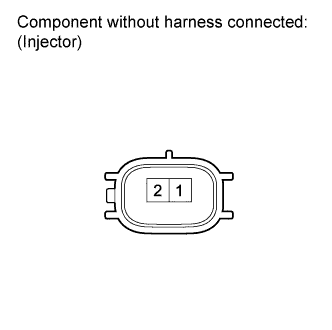
| 1.INSPECT INJECTOR ASSEMBLY |
Disconnect the injector connectors.
Measure the resistance according to the value(s) in the table below.
- Standard resistance:
Tester Connection
| Condition
| Specified Condition
|
1 - 2
| 20°C (68°F)
| 0.85 to 1.05 Ω
|
Reconnect the injector connectors.
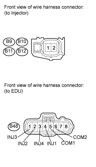
| 2.CHECK HARNESS AND CONNECTOR (INJECTOR - EDU) |
Disconnect the injector connectors.
Disconnect the EDU connector.
Measure the resistance according to the value(s) in the table below.
- Standard resistance (Check for open):
Tester Connection
| Condition
| Specified Condition
|
B9-1 - B48-4 (INJ1)
| Always
| Below 1 Ω
|
B11-1 - B48-2 (INJ2)
| Always
| Below 1 Ω
|
B10-1 - B48-1 (INJ3)
| Always
| Below 1 Ω
|
B12-1 - B48-3 (INJ4)
| Always
| Below 1 Ω
|
B9-2 - B48-5 (COM1)
| Always
| Below 1 Ω
|
B10-2 - B48-6 (COM2)
| Always
| Below 1 Ω
|
B11-2 - B48-6 (COM2)
| Always
| Below 1 Ω
|
B12-2 - B48-5 (COM1)
| Always
| Below 1 Ω
|
- Standard resistance (Check for short):
Tester Connection
| Condition
| Specified Condition
|
B9-1 or B48-4 (INJ1) - Body ground
| Always
| 10 kΩ or higher
|
B11-1 or B48-2 (INJ2) - Body ground
| Always
| 10 kΩ or higher
|
B10-1 or B48-1 (INJ3) - Body ground
| Always
| 10 kΩ or higher
|
B12-1 or B48-3 (INJ4) - Body ground
| Always
| 10 kΩ or higher
|
B9-2 or B48-5 (COM1) - Body ground
| Always
| 10 kΩ or higher
|
B10-2 or B48-6 (COM2) - Body ground
| Always
| 10 kΩ or higher
|
B11-2 or B48-6 (COM2) - Body ground
| Always
| 10 kΩ or higher
|
B12-2 or B48-5 (COM1) - Body ground
| Always
| 10 kΩ or higher
|
Reconnect the injector connectors.
Reconnect the EDU connector.
| | REPAIR OR REPLACE HARNESS OR CONNECTOR (INJECTOR - EDU) |
|
|
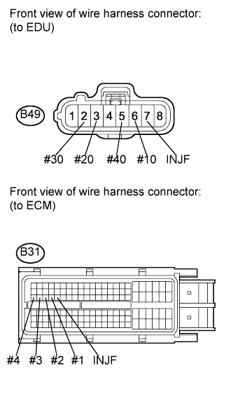
| 3.CHECK HARNESS AND CONNECTOR (EDU - ECM) |
Disconnect the EDU connector.
Disconnect the ECM connector.
Measure the resistance according to the value(s) in the table below.
- Standard resistance (Check for open):
Tester Connection
| Condition
| Specified Condition
|
B49-6 (#10) - B31-50 (#1)
| Always
| Below 1 Ω
|
B49-3 (#20) - B31-49 (#2)
| Always
| Below 1 Ω
|
B49-2 (#30) - B31-48 (#3)
| Always
| Below 1 Ω
|
B49-5 (#40) - B31-47 (#4)
| Always
| Below 1 Ω
|
B49-7 (INJF) - B31-51 (INJF)
| Always
| Below 1 Ω
|
- Standard resistance (Check for short):
Tester Connection
| Condition
| Specified Condition
|
B49-6 (#10) or B31-50 (#1) - Body ground
| Always
| 10 kΩ or higher
|
B49-3 (#20) or B31-49 (#2) - Body ground
| Always
| 10 kΩ or higher
|
B49-2 (#30) or B31-48 (#3) - Body ground
| Always
| 10 kΩ or higher
|
B49-5 (#40) or B31-47 (#4) - Body ground
| Always
| 10 kΩ or higher
|
B49-7 (INJF) or B31-51 (INJF) - Body ground
| Always
| 10 kΩ or higher
|
Reconnect the EDU connector.
Reconnect the ECM connector.
| | REPAIR OR REPLACE HARNESS OR CONNECTOR (EDU - ECM) |
|
|
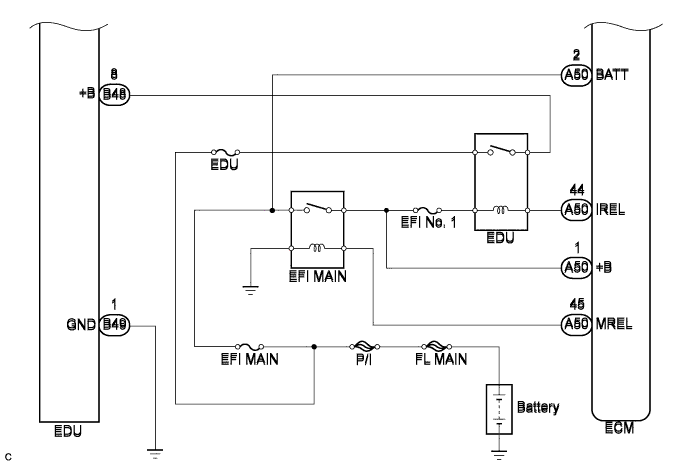
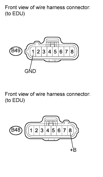
| 4.CHECK TERMINAL VOLTAGE EDU POWER SOURCE |
Disconnect the EDU connectors.
Turn the ignition switch on (IG).
Measure the voltage according to the value(s) in the table below.
- Standard voltage:
Tester Connection
| Switch Condition
| Specified Condition
|
B48-8 (+B) - B49-1 (GND)
| Ignition switch on (IG)
| 11 to 14 V
|
Reconnect the EDU connectors.
Replace the EDU (See page Нажмите здесь).
| 6.CHECK WHETHER DTC OUTPUT RECURS |
Connect the intelligent tester to the DLC3.
Turn the ignition switch on (IG) and turn the tester on.
Clear the DTCs (See page Нажмите здесь).
Start the engine and drive the vehicle for approximately 15 minutes.
Enter the following menus: Powertrain / Engine and ECT / DTC.
Read the DTCs.
- Result:
Result
| Proceed to
|
DTC P0200 is output
| A
|
DTC is not output
| B
|
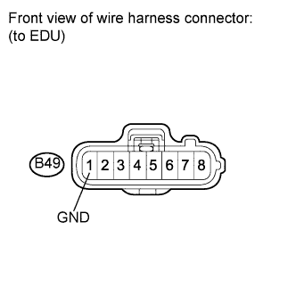
| 7.CHECK HARNESS AND CONNECTOR (EDU - BODY GROUND) |
Disconnect the EDU connector.
Measure the resistance according to the value(s) in the table below.
- Standard resistance:
Tester Connection
| Condition
| Specified Condition
|
B49-1 (GND) - Body ground
| Always
| Below 1 Ω
|
Reconnect the EDU connector.
| | REPAIR OR REPLACE HARNESS OR CONNECTOR (EDU - BODY GROUND) |
|
|
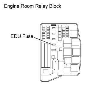
Remove the EDU fuse from the engine room relay block.
Measure the resistance according to the value(s) in the table below.
- Standard resistance:
Tester Connection
| Condition
| Specified Condition
|
EDU fuse
| Always
| Below 1 Ω
|
Reinstall the EDU fuse.
| 9.INSPECT INTEGRATION RELAY (EDU RELAY) |
Remove the integration relay from the engine room relay block.
Disconnect the integration relay connector.
Measure the resistance according to the value(s) in the table below.
- Standard resistance:
Tester Connection
| Condition
| Specified Condition
|
1E-1 - 1B-8
| Battery voltage is not applied between terminals 1B-6 and 1B-7
| 10 kΩ or higher
|
Battery voltage is applied between terminals 1B-6 and 1B-7
| Below 1 Ω
|
Reconnect the integration relay connector.
Reinstall the integration relay.
| | REPLACE INTEGRATION RELAY |
|
|
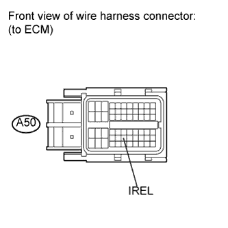
| 10.INSPECT ECM (IREL VOLTAGE) |
Disconnect the ECM connector.
Turn the ignition switch on (IG).
Measure the voltage according to the value(s) in the table below.
- Standard voltage:
Tester Connection
| Switch Condition
| Specified Condition
|
A50-44 (IREL) - Body ground
| Ignition switch on (IG)
| 11 to 14 V
|
Reconnect the ECM connector.
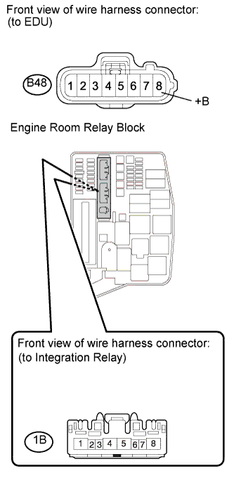
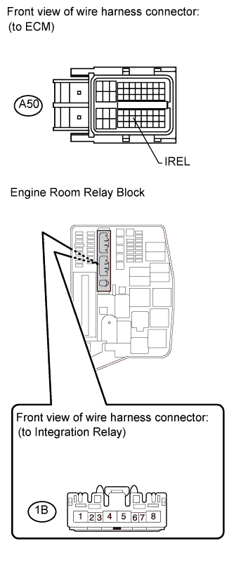
| 11.CHECK HARNESS AND CONNECTOR (EDU - EDU RELAY) |
Disconnect the EDU connector.
Remove the integration relay from the engine room relay block.
Disconnect the integration relay connector.
Measure the resistance according to the value(s) in the table below.
- Standard resistance (Check for open):
Tester Connection
| Condition
| Specified Condition
|
B48-8 (+B) - 1B-8
| Always
| Below 1 Ω
|
- Standard resistance (Check for short):
Tester Connection
| Condition
| Specified Condition
|
B48-8 (+B) or 1B-8 - Body ground
| Always
| 10 kΩ or higher
|
Reconnect the EDU connector.
Reconnect the integration relay connector.
Reinstall the integration relay.
| | REPAIR OR REPLACE HARNESS OR CONNECTOR (EDU - EDU RELAY) |
|
|
| OK |
|
|
|
| REPAIR OR REPLACE HARNESS OR CONNECTOR (BATTERY - EDU RELAY) |
|
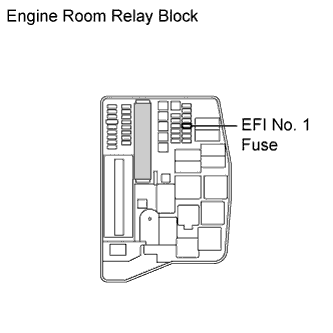
| 12.CHECK FUSE (EFI NO. 1 FUSE) |
Remove the EFI No. 1 fuse from the engine room relay block.
Measure the resistance according to the value(s) in the table below.
- Standard resistance:
Tester Connection
| Condition
| Specified Condition
|
EFI No. 1 fuse
| Always
| Below 1 Ω
|
Reinstall the EFI No. 1 fuse.
| | REPLACE FUSE (EFI NO. 1 FUSE) |
|
|
| 13.CHECK HARNESS AND CONNECTOR (ECM - EDU RELAY) |
Disconnect the ECM connector.
Remove the integration relay from the engine room relay block.
Disconnect the integration relay connector.
Measure the resistance according to the value(s) in the table below.
- Standard resistance (Check for open):
Tester Connection
| Condition
| Specified Condition
|
1B-7 - A50-44 (IREL)
| Always
| Below 1 Ω
|
- Standard resistance (Check for short):
Tester Connection
| Condition
| Specified Condition
|
1B-7 or A50-44 (IREL) - Body ground
| Always
| 10 kΩ or higher
|
Reconnect the ECM connector.
Reconnect the integration relay connector.
Reinstall the integration relay.
| | REPAIR OR REPLACE HARNESS OR CONNECTOR (ECM - EDU RELAY) |
|
|
| OK |
|
|
|
| REPAIR OR REPLACE HARNESS OR CONNECTOR (BATTERY - EDU RELAY) |
|