Dtc P0100 Mass Or Volume Air Flow Circuit. Corolla Auris
Двигатель. COROLLA, AURIS. ZZE150 ZRE151,152 NDE150
DESCRIPTION
WIRING DIAGRAM
INSPECTION PROCEDURE
READ VALUE USING INTELLIGENT TESTER (MASS AIR FLOW RATE)
INSPECT MASS AIR FLOW METER (POWER SOURCE CIRCUIT)
INSPECT MASS AIR FLOW METER (VG VOLTAGE)
CHECK HARNESS AND CONNECTOR (MASS AIR FLOW METER - ECM)
CHECK HARNESS AND CONNECTOR (SENSOR GROUND)
CHECK HARNESS AND CONNECTOR (MASS AIR FLOW METER - ECM)
DTC P0100 Mass or Volume Air Flow Circuit |
DTC P0102 Air Flow Meter Circuit Low Input |
DTC P0103 Air Flow Meter Circuit High Input |
DESCRIPTION
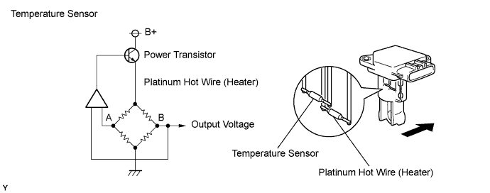
The mass air flow meter uses a platinum hot wire. The mass air flow meter consists of a platinum hot wire, a temperature sensor and a control circuit installed in a plastic housing. The mass air flow meter hot wire and temperature sensor (located in the intake air by-pass of the housing) detect changes in the intake air temperature.The hot wire is maintained at the predetermined temperature by controlling the current flow through the hot wire. This current flow is then related as the output voltage of the mass air flow meter.The circuit is constructed so that the platinum hot wire and temperature sensor provide a bridge circuit, with the power transistor controlled so that the potential of A and B remains equal to maintain the predetermined temperature.DTC No.
| DTC Detection Condition
| Trouble Area
|
P0100
| Open or short in mass air flow meter circuit for more than 3 seconds with engine speed at 4000 rpm or less
(1-trip detection logic)
| - Open or short in mass air flow meter circuit
- Mass air flow meter
- ECM
|
P0102
| Open in mass air flow meter circuit for more than 3 seconds with engine speed at 4000 rpm or less
(1-trip detection logic)
|
P0103
| Short in mass air flow meter circuit for more than 3 seconds with engine speed at 4000 rpm or less
(1-trip detection logic)
|
- УКАЗАНИЕ:
- After confirming DTC P0100, P0102, or P0103, check the mass air flow ratio by selecting the following menus on the intelligent tester: "Powertrain / Engine and ECT / Data List / MAF".
Reference:Air Flow Value (g/sec.)
| Malfunction
|
Approximately 0.0
| - Open in mass air flow meter power source circuit
- Open or short in VG circuit
|
174.0 or more
| Open in EVG circuit
|
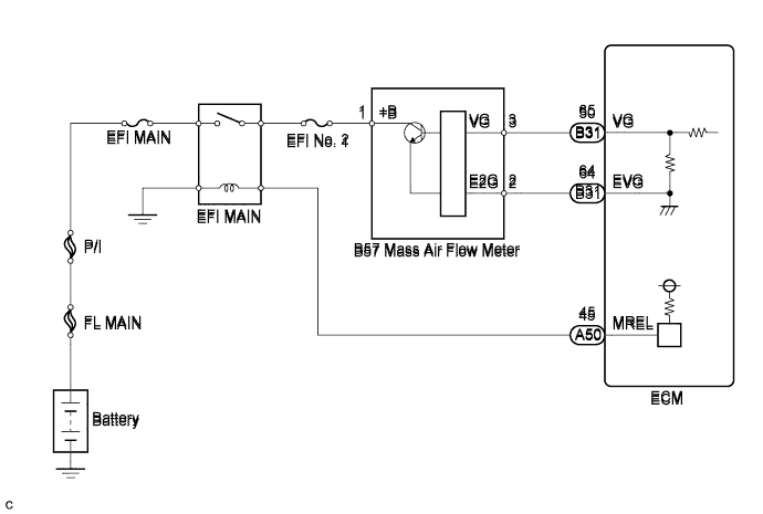
WIRING DIAGRAM
INSPECTION PROCEDURE
- ПРИМЕЧАНИЕ:
- After replacing the ECM, the new ECM needs registration (See page Нажмите здесь) and initialization (See page Нажмите здесь).
- УКАЗАНИЕ:
- Read freeze frame data using the intelligent tester. The ECM records vehicle and driving condition information as freeze frame data the moment a DTC is stored. When troubleshooting, freeze frame data can help determine if the vehicle was moving or stationary, if the engine was warmed up or not, and other data from the time the malfunction occurred.
| 1.READ VALUE USING INTELLIGENT TESTER (MASS AIR FLOW RATE) |
Connect the intelligent tester to the DLC3.
Start the engine and turn the tester on.
Enter the following menus: Powertrain / Engine and ECT / Data List / MAF.
Read the value.
- Result:
Result
| Proceed to
|
Air flow rate (g/sec.): 0.0
| A
|
Air flow rate (g/sec.): 174.0 or more
| B
|
Air flow rate (g/sec.): Between 1 and 173.0*
| C
|
- УКАЗАНИЕ:
- *: The value should change when the throttle valve is opened or closed.
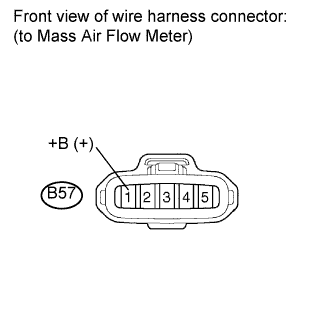
| 2.INSPECT MASS AIR FLOW METER (POWER SOURCE CIRCUIT) |
Disconnect the mass air flow meter connector.
Turn the ignition switch on (IG).
Measure the voltage according to the value(s) in the table below.
- Standard voltage:
Tester Connection
| Switch Condition
| Specified Condition
|
B57-1 (+B) - Body ground
| Ignition switch on (IG)
| 11 to 14 V
|
Reconnect the mass air flow meter connector.
| | REPAIR OR REPLACE HARNESS OR CONNECTOR (MASS AIR FLOW METER - BATTERY) |
|
|
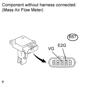
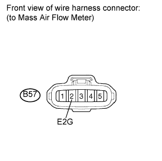
| 3.INSPECT MASS AIR FLOW METER (VG VOLTAGE) |
Disconnect the mass air flow meter connector.
Apply battery voltage across terminals +B and E2G.
Connect the positive (+) tester probe to terminal VG, and the negative (-) tester probe to terminal E2G.
Measure the voltage according to the value(s) in the table below.
- Standard voltage:
Tester Connection
| Switch Condition
| Specified Condition
|
B57-3 (VG) - B57-2 (E2G)
| Ignition switch on (IG)
| 0.2 to 4.9 V
|
Reconnect the mass air flow meter connector.
| 4.CHECK HARNESS AND CONNECTOR (MASS AIR FLOW METER - ECM) |
Disconnect the mass air flow meter connector.
Disconnect the ECM connector.
Measure the resistance according to the value(s) in the table below.
- Standard resistance (Check for open):
Tester Connection
| Condition
| Specified Condition
|
B57-3 (VG) - B31-65 (VG)
| Always
| Below 1 Ω
|
B57-2 (E2G) - B31-64 (EVG)
| Always
| Below 1 Ω
|
- Standard resistance (Check for short):
Tester Connection
| Condition
| Specified Condition
|
B57-3 (VG) or B31-65 (VG) - Body ground
| Always
| 10 kΩ or higher
|
Reconnect the mass air flow meter connector.
Reconnect the ECM connector.
| | REPAIR OR REPLACE HARNESS OR CONNECTOR (MASS AIR FLOW METER - ECM) |
|
|
| 5.CHECK HARNESS AND CONNECTOR (SENSOR GROUND) |
Disconnect the mass air flow meter connector.
Measure the resistance according to the value(s) in the table below.
- Standard resistance:
Tester Connection
| Condition
| Specified Condition
|
B57-2 (E2G) - Body ground
| Always
| Below 1 Ω
|
Reconnect the mass air flow meter connector.
| 6.CHECK HARNESS AND CONNECTOR (MASS AIR FLOW METER - ECM) |
Disconnect the mass air flow meter connector.
Disconnect the ECM connector.
Measure the resistance according to the value(s) in the table below.
- Standard resistance (Check for open):
Tester Connection
| Condition
| Specified Condition
|
B57-3 (VG) - B31-65 (VG)
| Always
| Below 1 Ω
|
B57-2 (E2G) - B31-64 (EVG)
| Always
| Below 1 Ω
|
- Standard resistance (Check for short):
Tester Connection
| Condition
| Specified Condition
|
B57-3 (VG) or B31-65 (VG) - Body ground
| Always
| 10 kΩ or higher
|
Reconnect the mass air flow meter connector.
Reinstall the ECM connector.
| | REPAIR OR REPLACE HARNESS OR CONNECTOR (MASS AIR FLOW METER - ECM) |
|
|