Двигатель. COROLLA, AURIS. ZZE150 ZRE151,152 NDE150
DESCRIPTION
MONITOR DESCRIPTION
WIRING DIAGRAM
INSPECTION PROCEDURE
INSPECT AIR FUEL RATIO SENSOR (HEATER RESISTANCE)
INSPECT TERMINAL VOLTAGE (+B OF AIR FUEL RATIO SENSOR)
CHECK HARNESS AND CONNECTOR (AIR FUEL RATIO SENSOR - ECM)
CHECK WHETHER DTC OUTPUT RECURS
INSPECT A/F RELAY
INSPECT TERMINAL VOLTAGE (A/F RELAY)
INSPECT TERMINAL VOLTAGE (A/F RELAY)
CHECK HARNESS AND CONNECTOR (AIR FUEL RATIO SENSOR - A/F RELAY)
CHECK HARNESS AND CONNECTOR (A/F RELAY - BODY GROUND)
CHECK FUSE (EFI NO. 1 FUSE)
CHECK FUSE (A/F FUSE)
DTC P0031 Oxygen (A/F) Sensor Heater Control Circuit Low (Bank 1 Sensor 1) |
DTC P0032 Oxygen (A/F) Sensor Heater Control Circuit High (Bank 1 Sensor 1) |
DESCRIPTION
- УКАЗАНИЕ:
- For more information on the air fuel ratio sensor and TOYOTA D-CAT*: (See page Нажмите здесь).
- This DTC is related to the air fuel ratio sensor, although the caption is the oxygen sensor.
- *: Diesel Clean Advanced Technology.
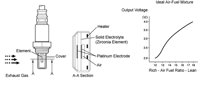
The characteristic of the air fuel ratio sensor is that it provides an output voltage (*1) that is proportional to the air-fuel ratio that it is measuring. The air fuel ratio sensor output voltage is used as feedback to allow the ECM to control the air fuel ratio mixture.The air fuel ratio sensor is located after the Diesel Particulate Filter (DPF) catalytic converter. This sensor has been developed based on the structure and technology of the air fuel ratio sensor that is used for gasoline engine. The cover for the sensor electrode has been modified to suit its application in a diesel engine. This change allows the sensor to function effectively in this TOYOTA D-CAT type diesel engine, and it also avoids problems with sensor temperature and particulate matter (PM).In order to reduce PM, the ECM adjusts the air-fuel ratio to a mixture that is slightly richer than that which would otherwise be used. (note that this mixture is still leaner than the stoichiometric air fuel ratio) The ECM performs these adjustments based on signals received from the air fuel ratio sensor.When the ECM performs DPF catalyst regeneration (cleaning) by adding fuel using the exhaust fuel addition injector, the air fuel ratio sensor feedback is used to ensure that an appropriate air fuel ratio is maintained.*1: This voltage change occurs only inside the computer. It is not possible to measure this voltage at the sensor. The intelligent tester can be used to monitor this voltage.- УКАЗАНИЕ:
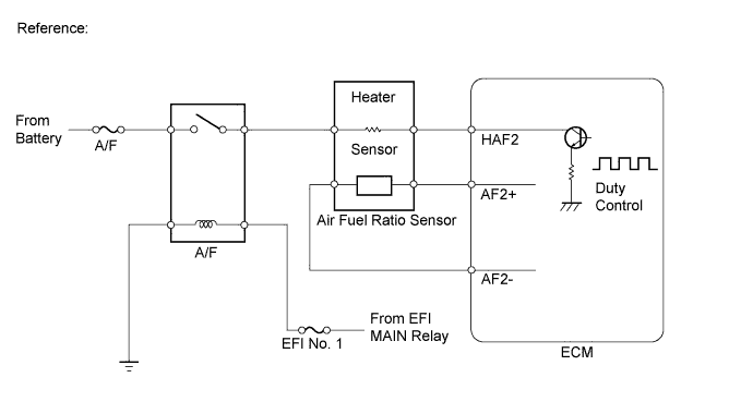
- The ECM provides a pulse width modulated control circuit to adjust current through the heater. The air fuel ratio sensor heater circuit uses a relay on the +B side of the circuit.
DTC No.
| DTC Detection Condition
| Trouble Area
|
P0031
| Air fuel ratio sensor heater current is 0.8 A or less when the heater operates
(1-trip detection logic)
| - Open in air fuel ratio sensor heater circuit
- Air fuel ratio sensor heater
- Air fuel ratio sensor heater relay
- ECM
|
P0032
| Air fuel ratio sensor heater current is 10.4 A or more when the heater operates
Air fuel ratio sensor heater current is 0.8 A or more when the heater does not operate
(1-trip detection logic)
| - Short in air fuel ratio sensor heater circuit
- Air fuel ratio sensor heater
- Air fuel ratio sensor heater relay
- ECM
|
MONITOR DESCRIPTION
The inner surface of the air fuel ratio sensor element is exposed to outside air. The outer surface of the sensor element is exposed to exhaust gases. The sensor element is made of platinum coated zirconia and includes an integrated heating element. The zirconia element generates a small voltage when there is a large difference in the oxygen concentrations of the exhaust and the outside air. The platinum coating amplifies the voltage generation. When heated, the sensor becomes very efficient. If the temperature of the exhaust is low, the sensor will not generate useful voltage signals without supplemental heating. The ECM regulates the supplemental heating by using a duty-cycle approach to regulate the average current in the heater element. If the heater current is out of the normal range, the sensor's output signals will be inaccurate and the ECM cannot regulate the air-fuel ratio properly. When the heater current is out of the normal operating range, the ECM interprets this as a malfunction and sets a DTC.
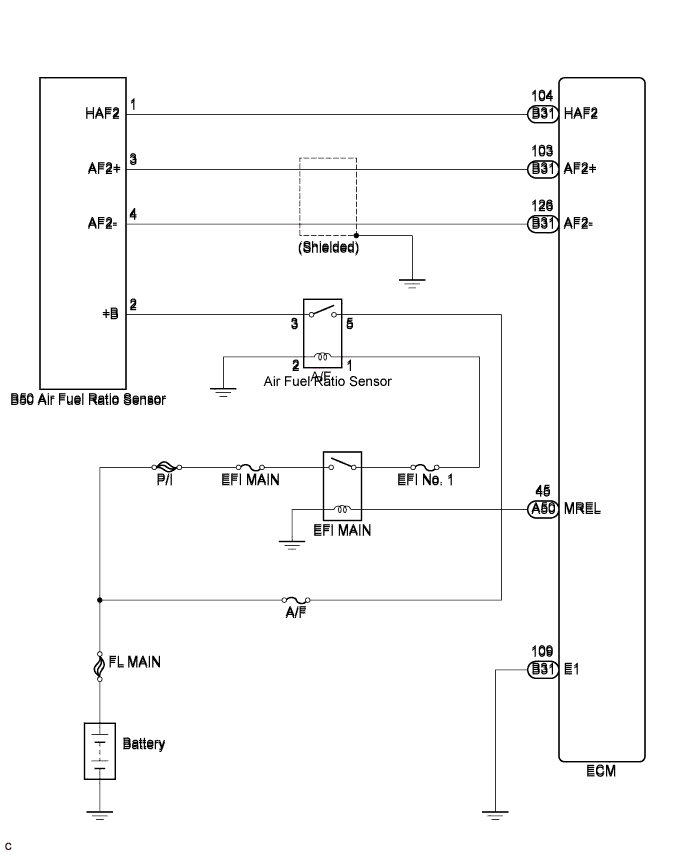
WIRING DIAGRAM
INSPECTION PROCEDURE
- ПРИМЕЧАНИЕ:
- After replacing the ECM, the new ECM needs registration (See page Нажмите здесь) and initialization (See page Нажмите здесь).
- УКАЗАНИЕ:
- Read freeze frame data using the intelligent tester. The ECM records vehicle and driving condition information as freeze frame data the moment a DTC is stored. When troubleshooting, freeze frame data can help determine if the vehicle was moving or stationary, if the engine was warmed up or not, and other data from the time the malfunction occurred.
| 1.INSPECT AIR FUEL RATIO SENSOR (HEATER RESISTANCE) |
Disconnect the air fuel ratio sensor connector.
Measure the resistance according to the value(s) in the table below.
- Standard resistance:
Tester Connection
| Condition
| Specified Condition
|
1 (HAF2) - 2 (+B)
| 20°C (68°F)
| 1.8 to 3.4 Ω
|
Reconnect the air fuel ratio sensor connector.
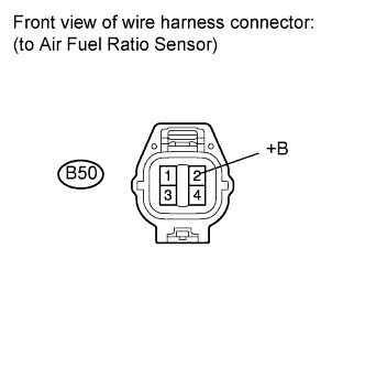
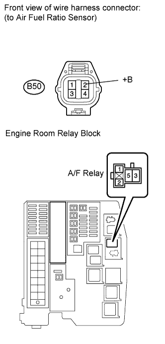
| 2.INSPECT TERMINAL VOLTAGE (+B OF AIR FUEL RATIO SENSOR) |
Disconnect the air fuel ratio sensor connector.
Turn the ignition switch on (IG).
Measure the voltage according to the value(s) in the table below.
- Standard voltage:
Tester Connection
| Switch Condition
| Specified Condition
|
B50-2 (+B) - Body ground
| Ignition switch on (IG)
| 11 to 14 V
|
Reconnect the air fuel ratio sensor connector.
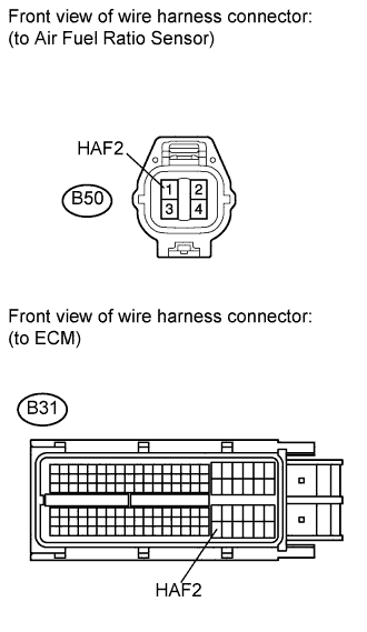
| 3.CHECK HARNESS AND CONNECTOR (AIR FUEL RATIO SENSOR - ECM) |
Disconnect the air fuel ratio sensor connector.
Disconnect the ECM connector.
Measure the resistance according to the value(s) in the table below.
- Standard resistance (Check for open):
Tester Connection
| Condition
| Specified Condition
|
B50-1 (HAF2) - B31-104 (HAF2)
| Always
| Below 1 Ω
|
- Standard resistance (Check for short):
Tester Connection
| Condition
| Specified Condition
|
B50-1 (HAF2) or B31-104 (HAF2) - Body ground
| Always
| 10 kΩ or higher
|
Reconnect the air fuel ratio sensor.
Reconnect the ECM connector.
| | REPAIR OR REPLACE HARNESS OR CONNECTOR (AIR FUEL RATIO SENSOR - ECM) |
|
|
| 4.CHECK WHETHER DTC OUTPUT RECURS |
Connect the intelligent tester to the DLC3.
Turn the ignition switch on (IG) and turn the tester on.
Clear the DTCs (See page Нажмите здесь).
Start the engine.
Allow the engine to idle for 1 minute or more.
Select the following menu items: Powertrain / Engine and ECT / DTC.
Read the DTCs.
- Result:
Result
| Proceed to
|
DTC is not output
| A
|
DTC P0031 and/or P0032 are output
| B
|
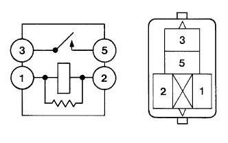
Remove the A/F relay from the engine room relay block.
Inspect the A/F relay.
- Standard resistance:
Tester Connection
| Condition
| Specified Condition
|
3 - 5
| Battery voltage is not applied between terminals 1 and 2
| 10 kΩ or higher
|
Battery voltage is applied between terminals 1 and 2
| Below 1 Ω
|
Reinstall the A/F relay.
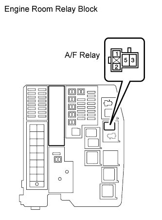
| 6.INSPECT TERMINAL VOLTAGE (A/F RELAY) |
Remove the A/F relay from the engine room relay block.
Measure the voltage according to the value(s) in the table below.
- Standard voltage:
Tester Connection
| Switch Condition
| Specified Condition
|
5 (A/F relay) - Body ground
| Always
| 11 to 14 V
|
Reinstall the A/F relay.
| 7.INSPECT TERMINAL VOLTAGE (A/F RELAY) |
Remove the A/F relay from the engine room relay block.
Turn the ignition switch on (IG).
Measure the voltage according to the value(s) in the table below.
- Standard voltage:
Tester Connection
| Switch Condition
| Specified Condition
|
1 (A/F relay) - Body ground
| Ignition switch on (IG)
| 11 to 14 V
|
Reinstall the A/F relay.
| 8.CHECK HARNESS AND CONNECTOR (AIR FUEL RATIO SENSOR - A/F RELAY) |
Disconnect the air fuel ratio sensor connector.
Remove the A/F relay from the engine room relay block.
Measure the resistance according to the value(s) in the table below.
- Standard resistance (Check for open):
Tester Connection
| Condition
| Specified Condition
|
B50-2 (+B) - 3 (A/F relay)
| Always
| Below 1 Ω
|
- Standard resistance (Check for short):
Tester Connection
| Condition
| Specified Condition
|
B50-2 (+B) or 3 (A/F relay) - Body ground
| Always
| 10 kΩ or higher
|
Reconnect the air fuel ratio sensor connector.
Reinstall the A/F relay.
| | REPAIR OR REPLACE HARNESS OR CONNECTOR (AIR FUEL RATIO SENSOR - A/F RELAY) |
|
|
| 9.CHECK HARNESS AND CONNECTOR (A/F RELAY - BODY GROUND) |
Remove the A/F relay from the engine room relay block.
Measure the resistance according to the value(s) in the table below.
- Standard resistance:
Tester Connection
| Condition
| Specified Condition
|
2 (A/F relay) - Body ground
| Always
| Below 1 Ω
|
Reinstall the A/F relay.
| | REPAIR OR REPLACE HARNESS OR CONNECTOR (A/F RELAY - BODY GROUND) |
|
|
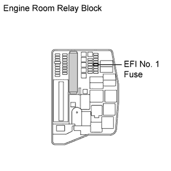
| 10.CHECK FUSE (EFI NO. 1 FUSE) |
Remove the EFI No. 1 fuse from the engine room relay block.
Measure the resistance according to the value(s) in the table below.
- Standard resistance:
Tester Connection
| Condition
| Specified Condition
|
EFI No. 1 fuse
| Always
| Below 1 Ω
|
Reinstall the EFI No. 1 fuse.
| | REPLACE FUSE (EFI NO. 1 FUSE) |
|
|
| OK |
|
|
|
| REPAIR OR REPLACE HARNESS OR CONNECTOR (A/F RELAY - BATTERY) |
|
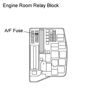
Remove the A/F fuse from the engine room relay block.
Measure the resistance according to the value(s) in the table below.
- Standard resistance:
Tester Connection
| Condition
| Specified Condition
|
A/F fuse
| Always
| Below 1 Ω
|
Reinstall the A/F fuse.
| OK |
|
|
|
| REPAIR OR REPLACE HARNESS OR CONNECTOR (A/F RELAY - BATTERY) |
|