Форсунка Добавления Отработавшего Топлива -- Установка |
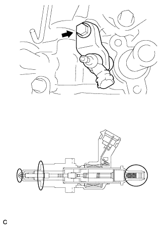
| 1. INSTALL EXHAUST FUEL ADDITION INJECTOR ASSEMBLY |
Install a new gasket, exhaust fuel addition injector and nozzle holder clamp with the washer and bolt.
- Момент затяжки:
- 29 Н*м{296 кгс*см, 21 фунт-сила-футов}
- ПРИМЕЧАНИЕ:
- Do not use an injector which has been dropped.
- Do not damage the areas indicated in the illustration.
- Do not allow the areas indicated in the illustration to be contaminated.
- УКАЗАНИЕ:
- Install the nozzle holder clamp while holding it.
 |
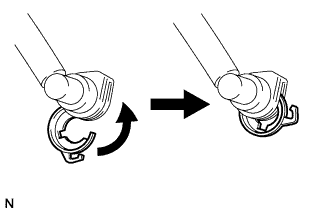
| 2. INSTALL FUEL TUBE SUB-ASSEMBLY |
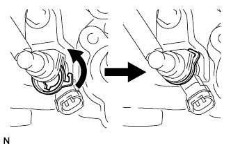
Turn the retainer in the direction indicated by the arrow until the retainer stops.
 |
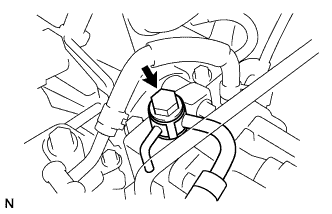
Install the fuel tube sub-assembly and a new gasket with the union bolt.
- Момент затяжки:
- 23 Н*м{235 кгс*см, 17 фунт-сила-футов}
 |
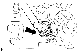
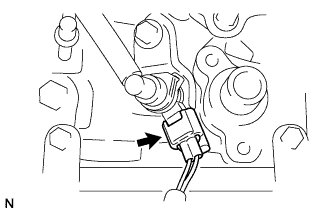
Insert the fuel tube connector into the injector.
 |
Turn the retainer in the direction indicated by the arrow until it makes a "click" sound.
- ПРИМЕЧАНИЕ:
- If the fuel tube connector is not inserted to the correct position of the injector, the retainer cannot be turned further in the direction of the arrow.
 |
Connect the exhaust fuel addition injector connector.
 |
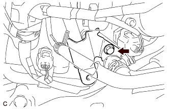
| 3. INSTALL FUEL HOSE PROTECTOR |
Install the fuel hose protector with the bolt.
- Момент затяжки:
- 21 Н*м{210 кгс*см, 15 фунт-сила-футов}
 |
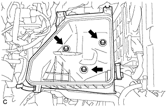
| 4. INSTALL AIR CLEANER CASE |
Install the 3 bolts and air cleaner case.
- Момент затяжки:
- 7.0 Н*м{71 кгс*см, 62 фунт-сила-дюймов}
 |
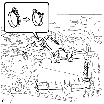
| 5. INSTALL AIR CLEANER CAP SUB-ASSEMBLY |
Install the air cleaner filter element.
Install the air cleaner cap sub-assembly, and connect the 2 clamps and band.
 |
Connect the No. 2 ventilation hose.
Connect the mass air flow meter connector.
| 6. INSTALL NO. 1 ENGINE COVER |
Attach the 4 clips to install the engine cover.
 |
| 7. INSPECT FOR FUEL LEAK |
PERFORM ACTIVE TEST
Connect the intelligent tester to the DLC3.
Turn the ignition switch to the ON position.
Turn the intelligent tester on.
Enter the following menus: Powertrain / Engine / Active Test.
Perform the Active Test.
Tester Display Test Part Control Range Diagnostic Notes Test the Fuel Leak Pressurizing common rail internal fuel pressure, and checking for fuel leaks. Stop/Start - Fuel pressure inside common rail is pressurized to specified value and engine speed is increased to 2000 rpm when ON is selected.
- Above conditions are maintained while test is ON.
- Fuel pressure inside common rail is pressurized to specified value and engine speed is increased to 2000 rpm when ON is selected.