Dtc P0885 Tcm Power Relay Control Circuit (Open). Corolla ZZE150
DESCRIPTION
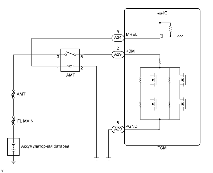
WIRING DIAGRAM
INSPECTION PROCEDURE
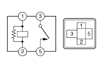
INSPECT AMT RELAY
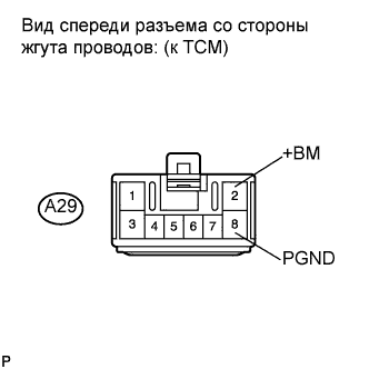
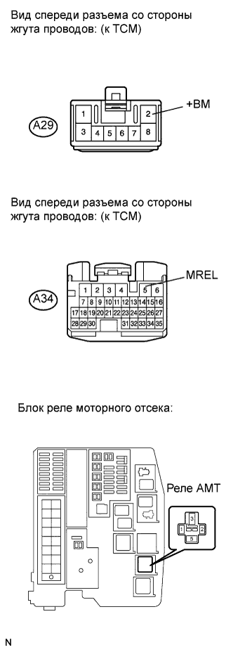
INSPECT TCM (+BM TERMINAL INPUT VOLTAGE)
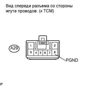
CHECK HARNESS AND CONNECTOR (TCM - BODY GROUND)
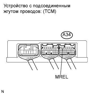
INSPECT TCM (MREL TERMINAL OUTPUT VOLTAGE)
CHECK HARNESS AND CONNECTOR (TCM - AMT RELAY)
CHECK HARNESS AND CONNECTOR (BATTERY - AMT RELAY)
CHECK HARNESS AND CONNECTOR (AMT RELAY - BODY GROUND)
DTC P0885 TCM Power Relay Control Circuit (Open) |
DTC P0887 TCM Power Relay Control Circuit (Short) |
DESCRIPTION
The multi-mode manual transaxle system has a dedicated power supply circuit. While the ignition switch is turned on (IG), the TCM outputs the power from the MREL terminal to operate the AMT relay. Then, the power is supplied to the +BM terminal of the TCM through the AMT relay. The voltage (+BM) is monitored and when it is low (6.29 V or less) despite the voltage being supplied to the MREL circuit, the TCM determines that there is a malfunction in the multi-mode manual transaxle system and sets a DTC. When the voltage (+BM) is high (6.29 V or more) although the voltage is not supplied to the MREL circuit, the TCM sets a DTC. DTC No.
| DTC Detecting Condition
| Trouble Area
|
P0885
| The TCM detects the following conditions simultaneously:
(1-trip detection logic)
- Voltage is supplied to MREL circuit
- +BM voltage is less than 6.29 V for 0.5 seconds
| - AMT fuse
- AMT relay
- Open in MREL signal circuit
- Open in PGND signal circuit
- Open in +BM signal circuit
- TCM
|
P0887
| The TCM detects the following conditions simultaneously:
(1-trip detection logic)
- No voltage is supplied to MREL circuit
- +BM voltage is more than 6.29 V for 0.5 seconds
| - AMT relay
- Short in MREL signal circuit
- Short in PGND signal circuit
- Short in +BM signal circuit
- TCM
|
WIRING DIAGRAM
INSPECTION PROCEDURE
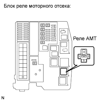
Remove the AMT relay from the engine room R/B.
Measure the resistance according to the value(s) in the table below.
- Standard resistance:
Tester Connection
| Condition
| Specified Condition
|
3 - 5
| Voltage is not applied between terminals 1 and 2
| 10 kΩ or higher
|
3 - 5
| Apply the battery voltage between terminals 1 and 2
| Below 1 Ω
|
Reinstall the AMT relay.
| 2.INSPECT TCM (+BM TERMINAL INPUT VOLTAGE) |
Disconnect the TCM connector.
Measure the voltage between the terminal of the TCM and the body ground when the ignition switch is turned on (IG) and off.
- Standard voltage:
Tester Connection
| Switch Condition
| Specified Condition
|
A29-2 (+BM) - A29-8 (PGND)
| Ignition switch off
| Below 1 V
|
A29-2 (+BM) - A29-8 (PGND)
| Ignition switch on (IG)
| 11 to 14 V
|
- Result:
Reconnect the TCM connector.
| 3.CHECK HARNESS AND CONNECTOR (TCM - BODY GROUND) |
Disconnect the TCM connector.
Measure the resistance according to the value(s) in the table below.
- Standard resistance:
Tester Connection
| Condition
| Specified Condition
|
A29-8 (PGND) - Body ground
| Always
| Below 1 Ω
|
Reconnect the TCM connector.
| | REPAIR OR REPLACE HARNESS OR CONNECTOR |
|
|
| 4.INSPECT TCM (MREL TERMINAL OUTPUT VOLTAGE) |
Measure the voltage between the terminal of the TCM and the body ground when the ignition switch is turned on (IG) and off.
- Standard voltage:
Tester Connection
| Switch Condition
| Specified Condition
|
A34-5 (MREL) - Body ground
| Ignition switch off
| Below 1 V
|
A34-5 (MREL) - Body ground
| Ignition switch on (IG)
| 11 to 14 V
|
| 5.CHECK HARNESS AND CONNECTOR (TCM - AMT RELAY) |
Disconnect the TCM connectors.
Turn the ignition switch off.
Remove the AMT relay from the engine room R/B.
Measure the resistance according to the value(s) in the table below.
- Standard resistance (Check for open):
Tester Connection
| Condition
| Specified Condition
|
A34-5 (MREL) - AMT relay (1)
| Always
| Below 1 Ω
|
A29-2 (+BM) - AMT relay (5)
| ↑
| Below 1 Ω
|
- Standard resistance (Check for short):
Tester Connection
| Condition
| Specified Condition
|
A34-5 (MREL) or AMT relay (1) - Body ground
| Always
| 10 kΩ or higher
|
A29-2 (+BM) or AMT relay (5) - Body ground
| ↑
| 10 kΩ or higher
|
Reconnect the TCM connectors.
Reinstall the relay.
| | REPAIR OR REPLACE HARNESS OR CONNECTOR |
|
|
| 6.CHECK HARNESS AND CONNECTOR (BATTERY - AMT RELAY) |
Remove the AMT relay from the engine room R/B.
Measure the voltage according to the value(s) in the table below.
- Standard voltage:
Tester Connection
| Condition
| Specified Condition
|
AMT relay (3) - Body ground
| Always
| 11 to 14 V
|
Reinstall the AMT relay.
| | REPAIR OR REPLACE HARNESS OR CONNECTOR |
|
|
| 7.CHECK HARNESS AND CONNECTOR (AMT RELAY - BODY GROUND) |
Remove the AMT relay from the engine room R/B.
Turn the ignition switch off.
Measure the resistance according to the value(s) in the table below.
- Standard resistance:
Tester Connection
| Condition
| Specified Condition
|
AMT relay (2) -Body ground
| Always
| Below 1 Ω
|
Reinstall the relay.
| | REPAIR OR REPLACE HARNESS OR CONNECTOR |
|
|