Трансмиссия. COROLLA, AURIS. ZZE150 ZRE151,152 NDE150
Механическая Трансмиссия 'Multimode' C53A. COROLLA, AURIS. ZZE150 ZRE151,152 NDE150
INSPECT SHIFT AND SELECT ACTUATOR ASSEMBLY
CHECK HARNESS AND CONNECTOR (SHIFT AND SELECT ACTUATOR - TCM)
DTC P0910 Gate Select Actuator Circuit |
DESCRIPTION
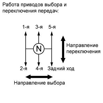
The shift and select actuator is operated by the TCM and changes the transaxle gear by moving the shift and select lever shaft. An electric motor (select motor) moves the shift and select lever shaft in the select direction, and the select stroke sensor, which is mounted on the shift and select actuator assembly, detects the select position. The TCM monitors the electrical current and select motor output terminal voltage, and detects malfunctions in the select motor circuit.
| DTC No. | DTC Detection Condition | Trouble Area |
| P0910 | The TCM detects the following conditions: (1-trip detection logic)
|
|
| P0910 | The TCM detects the following conditions: (1-trip detection logic)
|
|
| P0910 | The TCM detects the following conditions: (1-trip detection logic)
|
|
- *1: A short between the select motor circuit and the body ground is suspected.
- *2: A short between the select motor circuit and the +B circuit is suspected.
- *3: An open in the select motor circuit is suspected. When the motor current does not flow to the ECU terminals despite the ECU ordering the select motor to operate, the ECU sets the DTC.
- *4: An open in the select motor circuit is suspected. When the difference is more than the threshold despite the ECU not ordering the select motor to operate, the ECU sets the DTC.
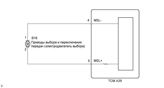
WIRING DIAGRAM
INSPECTION PROCEDURE
- ПРИМЕЧАНИЕ:
- In select stroke sensor or shift and select actuator assembly replacement, perform the [Initialization and Learning] procedure (See page Нажмите здесь) and [Synchronization Position Calibration] procedure (See page Нажмите здесь) after installing the sensor or actuator assembly. If the sensor or actuator is installed without performing [Initialization and Learning] and [Synchronization Position Calibration], it may cause driving performance degradation or system component breakage.
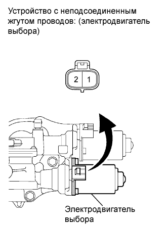
| 1.INSPECT SHIFT AND SELECT ACTUATOR ASSEMBLY |
Disconnect the select motor connector.
 |
Measure the select motor resistance.
- Standard resistance:
Tester Connection Condition Specified Condition 1 - 2 Always 0.1 to 100 Ω
Reconnect the select motor connector.
|
| ||||
| OK | |
| 2.CHECK HARNESS AND CONNECTOR (SHIFT AND SELECT ACTUATOR - TCM) |
Disconnect the select motor connector.
 |
Disconnect the TCM connector.
Measure the resistance according to the value(s) in the table below.
- Standard resistance:
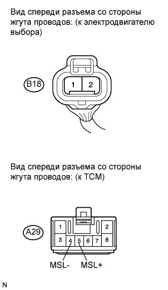
Tester Connection Condition Specified Condition A29-4 (MSL-) - B18-1 Always Below 1 Ω A29-5 (MSL+) - B18-2 ↑ Below 1 Ω A29-4 (MSL-) - Body ground ↑ 10 kΩ or higher A29-5 (MSL+) - Body ground ↑ 10 kΩ or higher
Reconnect the select motor connector.
Reconnect the TCM connector
|
| ||||
| OK | ||
| ||