READ VALUE USING INTELLIGENT TESTER
INSPECT SHIFT LEVER POSITION SENSOR
CHECK HARNESS AND CONNECTOR (SHIFT LEVER POSITION SENSOR - TCM)
CHECK HARNESS AND CONNECTOR (SHIFT LEVER POSITION SENSOR - BODY GROUND)
DTC P0820 Gear Lever "X-Y" Position Sensor Circuit |
DESCRIPTION
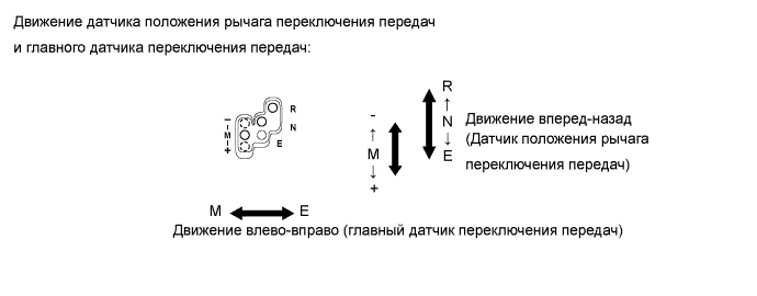
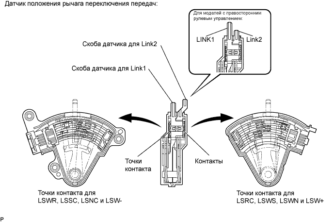
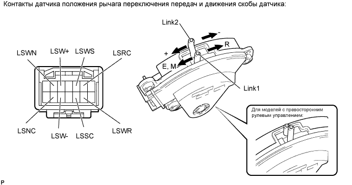
The TCM detects the shift lever position using the shift lever position sensor. The shift lever position sensor has two functions; detection and monitoring.The shift lever position sensor consists of a Link 1 circuit that detects the shift lever positions, R, N, E and M, and a Link 2 circuit that detects the [+] and [-] positions. The circuits are connected to the shift lever via the respective links. The contact switches (6-contact switch for Link 1, and 2-contact switch for Link 2) of the circuits turn on and off in accordance with the fore-aft movement of the shift lever. The TCM detects the present shift lever position in accordance with the ON/OFF status of these contact switches. The transmission shift main switch detects the side-to-side movement of the shift lever. It turns off when the shift lever is in the R, N, or E position, and turns on in the M, [+], or [-] position.
The shift lever position sensor and the transmission shift main switch convert the shift lever position into electric signals and output them to the TCM. The TCM detects the present shift lever position from these signals and operates the actuators to change the gear position.
| Contact Points | Shift Lever Position | ||||||
| R | N | E | M | - | + | ||
| Link 1 | LSRC | OFF | ON | ON | ON | ON | ON |
| LSWR | ON | OFF | OFF | OFF | OFF | OFF | |
| LSSC | ON | ON | OFF | OFF | OFF | OFF | |
| LSWS | OFF | OFF | ON | ON | ON | ON | |
| LSNC | ON | OFF | ON | ON | ON | ON | |
| LSWN | OFF | ON | OFF | OFF | OFF | OFF | |
| Link 2 | LSW- | OFF | OFF | OFF | OFF | ON | OFF |
| LSW+ | OFF | OFF | OFF | OFF | OFF | ON | |
| Transmission Shift Main Switch | OFF | OFF | OFF | ON | ON | ON | |
- УКАЗАНИЕ:
- The monitor runs when the shift lever is moved through each position (N, R, E, M, - and +).
| DTC No. | DTC Detection Condition | Trouble Area |
| P0820 | The TCM detects one of the following conditions: (1-trip detection logic)
|
|
| P0820 | The TCM detects one of the following conditions: (1-trip detection logic)
|
|
| P0820 | The TCM detects one of the following conditions: (1-trip detection logic)
|
|
| P0820 | The TCM detects the following conditions simultaneously: (1-trip detection logic)
|
|
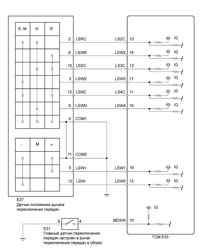
WIRING DIAGRAM
INSPECTION PROCEDURE
| 1.READ VALUE USING INTELLIGENT TESTER |
Connect the intelligent tester to the DLC3.
Turn the ignition switch on (IG) and the tester ON.
Select the following menu items: Powertrain / Multi-Mode M/T / Data List / Shift Lever Switch Signal 1 - 5, and Shift Lever Check Signal 1 - 3.
Check that the normal condition specified in the following table is shown on the display when moving the shift lever to each position R, N, E, M, +, and -.
Items
[Abbreviation]Measurement Items: Display Normal Conditions Diagnostic Notes Shift Lever Switch Signal1
[Shift SW Sig1]Shift lever switch signal (+):
Open (OFF) or Gnd (ON)Gnd: Shift lever position in (+)
Open: Other than aboveLSW1 (LSW+) terminal signal of TCM Shift Lever Switch Signal2
[Shift SW Sig2]Shift lever switch signal (R):
Open (OFF) or Gnd (ON)Gnd: Shift lever position in (R)
Open: Other than aboveLSW2 (LSWR) terminal signal of TCM Shift Lever Switch Signal3
[Shift SW Sig3]Shift lever switch signal (M) or (E):
Open (OFF) or Gnd (ON)Gnd: Shift lever position in (E), (M), (+) or (-)
Open: Shift lever position in (R) or (N)LSW3 (LSWS) terminal signal of TCM Shift Lever Switch Signal4
[Shift SW Sig4]Shift lever switch signal (N):
Open (OFF) or Gnd (ON)Gnd: Shift lever position in (N)
Open: Other than aboveLSW4 (LSWN) terminal signal of TCM Shift Lever Switch Signal5
[Shift SW Sig5]Shift lever switch signal (-):
Open (OFF) or Gnd (ON)Gnd: Shift lever position in (-)
Open: Other than aboveLSW5 (LSW-) terminal signal of TCM Shift Lever Check Signal1
[Shift Chek Sig1]Check signal of shift lever switch signal 2:
Open (ON) or Gnd (OFF)Open: Shift lever position in (R)
Gnd: Other than aboveLS2C (LSRC) terminal signal of TCM
Reversal signal of LSW2 (LSWR)
(ON and OFF reversed)Shift Lever Check Signal2
[Shift Chek Sig2]Check signal of shift lever switch signal 3:
Open (ON) or Gnd (OFF)Open: Shift lever position in (E), (M), (+) or (-)
Gnd: Shift lever position in (R) or (N)LS3C (LSSC) terminal signal of TCM
Reversal signal of LSW3 (LSWS)
(ON and OFF reversed)Shift Lever Check Signal3
[Shift Chek Sig3]Check signal of shift lever switch signal 4:
Open (ON) or Gnd (OFF)Open: Shift lever position in (N)
Gnd: Other than aboveLS4C (LSNC) terminal signal of TCM
Reversal signal of LSW4 (LSWN)
(ON and OFF reversed)- OK:
- When the shift lever is operated, the normal condition listed above is shown on the tester.
- Result:
Result Proceed to NG A OK B
|
| ||||
| A | |
| 2.INSPECT SHIFT LEVER POSITION SENSOR |
Disconnect the shift lever position sensor connector.
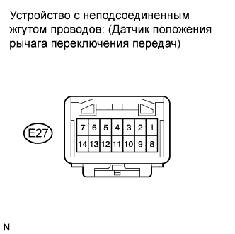 |
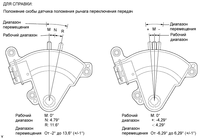
Check the resistance when the sensor handles move to the applicable position.
- УКАЗАНИЕ:
- The shift lever position sensor connector has no terminals in locations of 1, 8, 7, and 14.
- Standard Resistance:
Shift Lever Terminal Shift Lever Position Specified Condition 4 - 9, 4 - 10, 4 - 11, 4 - 13
9 - 10, 9 - 11, 9 - 13
10 - 11, 10 - 13
11 - 13R position Below 1 Ω 2 - 4, 2 - 6, 2 - 10, 2 - 11
4 - 6, 4 - 10, 4 - 11
6 - 10, 6 - 11
10 - 11N position Below 1 Ω 2 - 3, 2 - 4, 2 - 11, 2 - 13
3 - 4, 3 - 11, 3 - 13
4 - 11, 4 - 13
11 - 13E position Below 1 Ω 2 - 3, 2 - 4, 2 - 11, 2 - 13
3 - 4, 3 - 11, 3 - 13
4 - 11, 4 - 13
11 - 13M position Below 1 Ω 2 - 3, 2 - 4, 2 - 11, 2 - 13
3 - 4, 3 - 11, 3 - 13
4 - 5, 4 - 11, 4 - 13
5 - 11
11 - 13+ position Below 1 Ω 2 - 3, 2 - 4, 2 - 11, 2 - 13
3 - 4, 3 - 11, 3 - 13
4 - 11, 4 - 12, 4 - 13
11 - 12, 11 - 13- position Below 1 Ω
Reconnect the shift lever position sensor connector.
|
| ||||
| OK | |
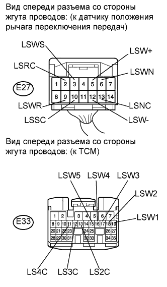
| 3.CHECK HARNESS AND CONNECTOR (SHIFT LEVER POSITION SENSOR - TCM) |
Disconnect the shift lever position sensor connector.
 |
Disconnect the TCM connector.
Measure the resistance according to the value(s) in the table below.
- Standard resistance:
Tester Connection Condition Specified Condition E33-19 (LSW1) - E27-5 (LSW+) Always Below 1 Ω E33-18 (LSW2) - E27-9 (LSWR) ↑ Below 1 Ω E33-17 (LSW3) - E27-3 (LSWS) ↑ Below 1 Ω E33-16 (LSW4) - E27-6 (LSWN) ↑ Below 1 Ω E33-15 (LSW5) - E27-12 (LSW-) ↑ Below 1 Ω E33-13 (LS2C) - E27-2 (LSRC) ↑ Below 1 Ω E33-12 (LS3C) - E27-10 (LSSC) ↑ Below 1 Ω E33-11 (LS4C) - E27-13 (LSNC) ↑ Below 1 Ω E33-19 (LSW1) - Body ground ↑ 10 kΩ or higher E33-18 (LSW2) - Body ground ↑ 10 kΩ or higher E33-17 (LSW3) - Body ground ↑ 10 kΩ or higher E33-16 (LSW4) - Body ground ↑ 10 kΩ or higher E33-15 (LSW5) - Body ground ↑ 10 kΩ or higher E33-13 (LS2C) - Body ground ↑ 10 kΩ or higher E33-12 (LS3C) - Body ground ↑ 10 kΩ or higher E33-11 (LS4C) - Body ground ↑ 10 kΩ or higher
Reconnect the shift lever position sensor connector.
Reconnect the TCM connector.
|
| ||||
| OK | |
| 4.CHECK HARNESS AND CONNECTOR (SHIFT LEVER POSITION SENSOR - BODY GROUND) |
Disconnect the shift lever position sensor connector.
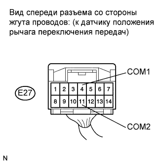 |
Measure the resistance according to the value(s) in the table below.
- Standard resistance:
Tester Connection Condition Specified Condition E27-4 (COM1) - Body ground Always Below 1 Ω E27-11 (COM2) - Body ground ↑ Below 1 Ω
Reconnect the shift lever position sensor connector.
|
| ||||
| OK | ||
| ||