CHECK ANY OTHER DTCS OUTPUT (IN ADDITION TO DTC P0725)
CHECK HARNESS AND CONNECTOR (TCM - ECM)
DTC P0725 Engine Speed Input Circuit |
DESCRIPTION
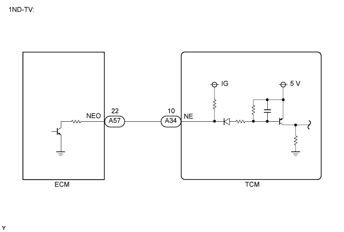
The ECM detects the engine revolution signals (NE) using the crankshaft position (CKP) sensor. The TCM controls the transaxle in accordance with two engine revolution signals. One signal is received directly from the ECM through a serial communication line. The other signal is received from the ECM via the Controller Area Network (CAN) communication. If the TCM detects no engine revolution signals despite the engine revolution signal via CAN being received while the vehicle is running, the ECU interprets this as a malfunction in the engine revolution signal circuit. The ECU sets the DTC and illuminates the multi-mode manual transmission warning light.| DTC No. | DTC Detection Condition | Trouble Area |
| P0725 | The TCM detects the following conditions simultaneously: (1-trip detection logic)
|
|
WIRING DIAGRAM
INSPECTION PROCEDURE
- ПРИМЕЧАНИЕ:
- In ECM replacement, perform the REGISTRATION (Injector compensation codes) after installing the ECM (for 1ND-TV) (See page Нажмите здесь)
| 1.CHECK ANY OTHER DTCS OUTPUT (IN ADDITION TO DTC P0725) |
Connect the intelligent tester to the DLC3.
Turn the ignition switch on (IG) and turn the tester ON.
Select the following menu items: Powertrain / Multi-Mode M/T / DTC.
Read DTCs and write them down.
Select the following menu items: Powertrain / Engine and ECT.
Read DTCs.
- Result:
Result Proceed to P0725 A P0725 and P0335 B
|
| ||||
| A | |
| 2.INSPECT TCM |
Connect the intelligent tester to the DLC3.
Turn the ignition switch on (IG) and turn the tester ON.
Select the following menu items: Powertrain / Multi-Mode M/T / Data List / Backup Engine Speed.
Check the engine speed value displayed on the tester.
Items
[Abbreviation]Measurement Items: Display Normal Conditions Diagnostic Notes Backup Engine Speed
[Bacup Engin Spd]Back-up engine speed:
Min.: 0 rpm, Max.: 8,160 rpm720 to 820 rpm: Idling
0 rpm: Engine stopped0 rpm displayed when malfunction in CAN communication
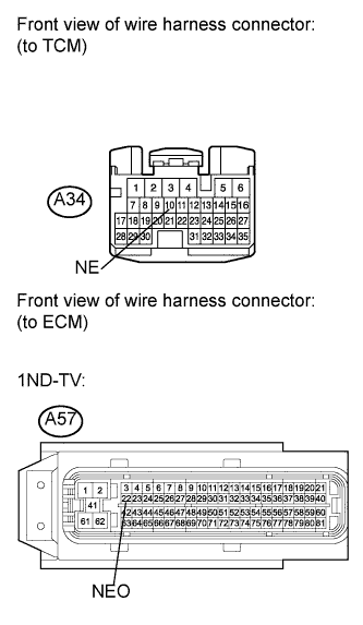
Connect the oscilloscope probes to the NE terminal and the body ground.
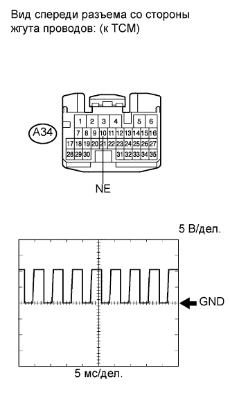 |
Check the signal waveform.
Tester settings Items Contents Terminals CH1: NE (A34-10) - Body ground Equipment Settings 5 V/DIV., 5 ms./DIV. Condition Engine idling - OK:
- When the Backup Engine Speed indicates an idling speed on the intelligent tester, a waveform similar to that in the illustration is output.
- Result:
Result Proceed to NG A OK B
|
| ||||
| A | |
| 3.CHECK HARNESS AND CONNECTOR (TCM - ECM) |
Disconnect the TCM connector.
 |
Disconnect the ECM connector.
Measure the resistance according to the value(s) in the table below.
- Standard resistance:
Tester connection Condition Specified Condition A34-10 (NE) - A57-22 (NEO) Always Below 1 Ω A34-10 (NE) - Body ground ↑ 10 kΩ or higher
Reconnect the TCM connector.
Reconnect the ECM connector.
|
| ||||
| OK | ||
| ||