Dtc P0703 Brake Switch B Circuit. Corolla ZZE150
DESCRIPTION
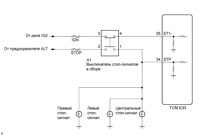
WIRING DIAGRAM
INSPECTION PROCEDURE
READ VALUE USING INTELLIGENT TESTER
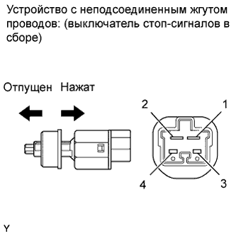
INSPECT STOP LIGHT SWITCH ASSEMBLY
CHECK HARNESS AND CONNECTOR (STOP LIGHT SWITCH - BATTERY)
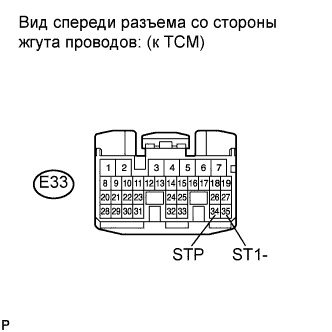
INSPECT TCM
DTC P0703 Brake Switch "B" Circuit |
DESCRIPTION
When the brake pedal is depressed, stop light switch signal STP turns on and stop light switch signal ST1- turns off. The TCM detects whether the brake pedal is depressed or released using those signal input. If the signal conditions, STP and ST1-, do not match the standard condition, the TCM interprets this as a malfunction in the stop light switch circuit and sets the DTC.DTC No.
| DTC Detection Condition
| Trouble Area
|
P0703
| Following conditions detected simultaneously for 1.0 second or more
(1-trip detection logic)
- Ignition switch on (IG)
- STP signal OFF
- ST1- signal OFF
| - Open or short in STP or ST1- signal circuits
- Stop light switch assembly
- TCM
|
WIRING DIAGRAM
INSPECTION PROCEDURE
| 1.READ VALUE USING INTELLIGENT TESTER |
Connect the intelligent tester to the DLC3.
Turn the ignition switch on (IG) and turn the tester ON.
Select the following menu items: Powertrain / Multi-Mode M/T / Data List / Brake Switch Signal1, Brake Switch Signal2 and STP Switch Signal.
Read the value, and check the stop light operation.
Items
[Abbreviation]
| Measurement Items: Display
| Normal Conditions
| Diagnostic Notes
|
Brake Switch Signal1
[Brake SW Sig1]
| Brake switch signal (STP):
Open (OFF) or Gnd (ON)
| Gnd: Brake pedal depressed
Open: Brake pedal released
| STP terminal signal of TCM
|
Brake Switch Signal2
[Brake SW Sig2]
| Brake switch signal (ST1-):
Open (OFF) or Gnd (ON)
| Open: Brake pedal depressed
Gnd: Brake pedal released
| ST1- terminal signal of TCM
|
- OK:
- The normal conditions listed above are shown on the tester when the brake pedal is operated.
- Result:
| 2.INSPECT STOP LIGHT SWITCH ASSEMBLY |
Disconnect the stop light switch assembly connector.
Measure the resistance according to the value(s) in the table below.
- Standard resistance:
Tester Connection
| Switch Position
| Specified Condition
|
1 - 2
| Switch pin released
| Below 1 Ω
|
3 - 4
| Switch pin released
| 10 kΩ or higher
|
1 - 2
| Switch pin pushed in
| 10 kΩ or higher
|
3 - 4
| Switch pin pushed in
| Below 1 Ω
|
Reconnect the stop light switch assembly connector.
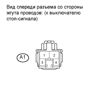
| 3.CHECK HARNESS AND CONNECTOR (STOP LIGHT SWITCH - BATTERY) |
Disconnect the stop light switch assembly connector.
Turn the ignition switch on (IG).
Measure the voltage between the terminals of the stop light switch assembly connector.
- Standard voltage:
Tester Connection
| Switch Condition
| Specified Condition
|
A1-2 - Body ground
| Ignition switch on (IG)
| 11 to 14 V
|
A1-3 - Body ground
| Ignition switch on (IG)
| 11 to 14 V
|
Reconnect the stop light switch assembly connector.
| | REPAIR OR REPLACE HARNESS OR CONNECTOR |
|
|
Disconnect the TCM connector.
Turn the ignition switch on (IG).
Measure the voltage between the terminals of the TCM connector.
- Standard voltage:
Tester Connection
| Pedal Condition
| Specified Condition
|
E33-34 (STP) - Body ground
| Depressed
| 11 to 14 V
|
E33-34 (STP) - Body ground
| Released
| Below 1 V
|
E33-35 (ST1-) - Body ground
| Depressed
| Below 1 V
|
E33-35 (ST1-) - Body ground
| Released
| 11 to 14 V
|
Reconnect the TCM connector.
| | REPAIR OR REPLACE HARNESS OR CONNECTOR (STOP LIGHT SWITCH - TCM) |
|
|