READ VALUE OF INTELLIGENT TESTER (VEHICLE SPEED)
CHECK COMBINATION METER SYSTEM
CHECK HARNESS AND CONNECTOR (TCM - COMBINATION METER)
CHECK HARNESS AND CONNECTOR (TCM - NO.4 JUNCTION BLOCK)
DTC P0500 Vehicle Speed Sensor "A" |
DESCRIPTION
Vehicles, which are equipped with the ABS (Anti-Lock Brake System), detect the vehicle speed using the skid control ECU and wheel speed sensor. The wheel speed sensor monitors the wheel rotation speed and sends a signal to the skid control ECU. The skid control ECU converts the wheel speed signal into a 4-pulse signal and transmits it to the TCM via the combination meter. The TCM determines the vehicle speed based on the frequency of the pulse signal.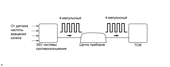
| DTC No. | DTC Detection Condition | Trouble Area |
| P0500 | The TCM detects the following conditions simultaneously for 4 seconds or more: (1-trip detection logic)
|
|
WIRING DIAGRAM
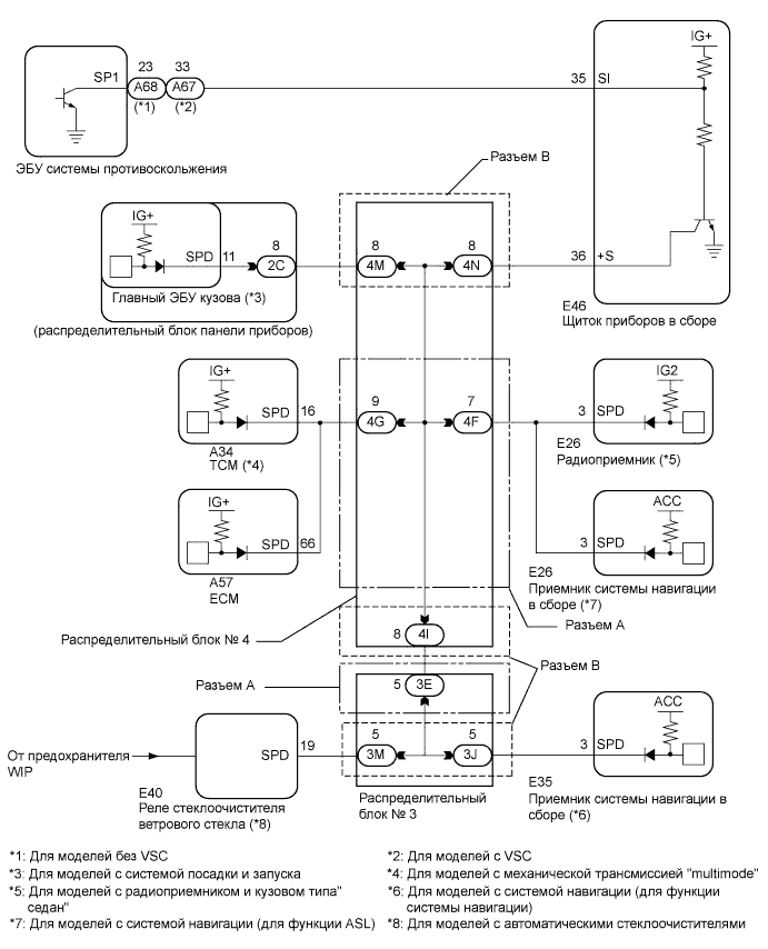
When a DTC P0500 is output, a ground short in the wiring of terminal SPD or an internal ground short in the relevant ECU is suspected.
INSPECTION PROCEDURE
| 1.READ VALUE OF INTELLIGENT TESTER (VEHICLE SPEED) |
Connect the intelligent tester to the DLC3.
Turn the ignition switch on (IG).
Turn the tester on.
Select the following menu items: Powertrain / Multi-Mode M/T / Data List / Vehicle Speed.
Drive the vehicle.
Read the value displayed on the tester.
- OK:
- Vehicle speeds displayed on tester and speedometer display are equal.
|
| ||||
| OK | ||
| ||
| 2.CHECK COMBINATION METER SYSTEM |
The circuits that send vehicle speed signals to this system are inspected in the meter system (See page Нажмите здесь).
During inspection for the meter section, if there is an instruction that indicates to go back to inspections for each system, proceed to the next step.
| NEXT | |
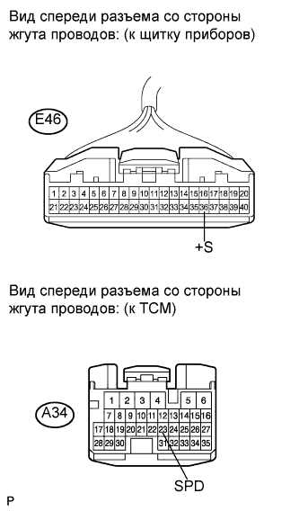
| 3.CHECK HARNESS AND CONNECTOR (TCM - COMBINATION METER) |
Disconnect the TCM connector.
 |
Disconnect the combination meter connector.
Measure the resistance according to the value(s) in the table below.
- Standard resistance (Check for open):
Tester Connection Condition Specified Condition E46-36 (+S) - A34-23 (SPD) Always Below 1 Ω
Reconnect the TCM connector.
Reconnect the combination meter connector.
|
| ||||
| OK | ||
| ||
| 4.CHECK HARNESS AND CONNECTOR (TCM - NO.4 JUNCTION BLOCK) |
Disconnect the TCM connector.
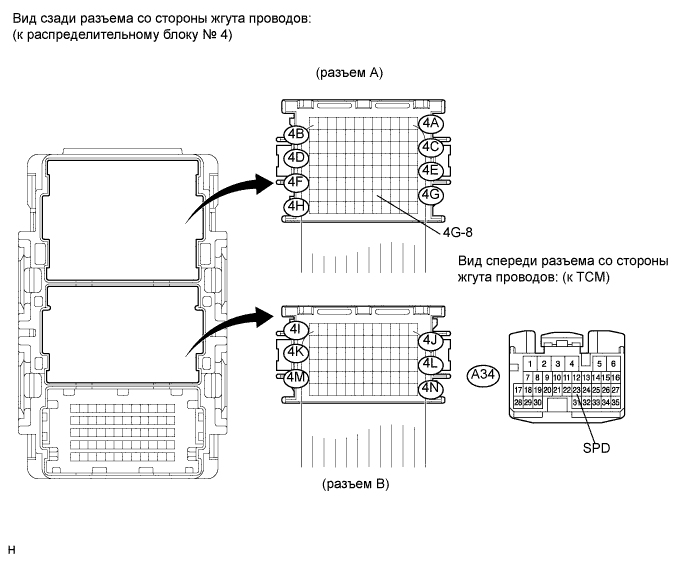
Disconnect the A connector from the No. 4 junction block.
Measure the resistance according to the value(s) in the table below.
- Standard resistance (Check for open):
Tester Connection Condition Specified Condition 4G-8 - A34-23 (SPD) Always Below 1 Ω
Reconnect the TCM connector.
Reconnect the A connector.
|
| ||||
| OK | ||
| ||