Стартер (Изготовление Tmc) -- Проверка |
| 1. INSPECT STARTER ASSEMBLY |
- ПРИМЕЧАНИЕ:
- The following tests must not be performed continuously for longer than 5 seconds to prevent the coil from burning out.
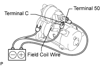
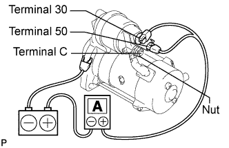
Perform a pull-in test.
Remove the nut and disconnect the lead wire from terminal C.
Connect the battery to the starter magnetic switch as shown in the illustration. Check that the clutch pinion gear is extended.
If the clutch pinion gear does not move, replace the magnet starter switch assembly.
 |
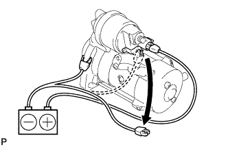
Perform a hold-in test.
Disconnect the negative (-) lead from terminal C. Check that the clutch pinion gear remains extended.
If the clutch pinion gear returns inward, replace the magnet starter switch assembly.
 |
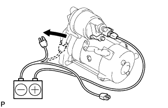
Check the operation.
Disconnect the negative (-) lead from the switch body. Check that the clutch pinion gear returns.
If the clutch pinion gear does not return inward, replace the magnet starter switch assembly.
 |
Perform a no-load performance test.
Connect the lead wire to terminal C. Make sure that the lead is not grounded.
- Момент затяжки:
- 5.9 Н*м{60 кгс*см, 52 фунт-сила-дюймов}
Clamp the starter in a vise.
Connect the battery and an ammeter to the starter as shown in the illustration.
Check that the starter rotates smoothly and steadily with the clutch pinion gear extended. Check that the ammeter reads the specified current.
- Standard current:
Tester Connection Condition Specified Condition Battery positive terminal - Terminal 30 - Terminal 50 11.5 V Below 190 A
 |
| 2. INSPECT STARTER ARMATURE ASSEMBLY |
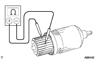
Inspect the resistance of the commutator.
Using an ohmmeter, measure the resistance between the segments of the commutator.
- Standard resistance:
Tester Connection Condition Specified Condition Segment - Segment - Below 1 Ω
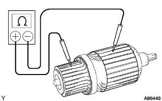
Using an ohmmeter, measure the resistance between the commutator and armature coil core.
- Standard resistance:
Tester Connection Condition Specified Condition Commutator - Armature coil core - 10 kΩ or higher
Check the surface of the commutator for dirt or burn.
If the surface is dirty or burnt, smooth it with 400-grit sandpaper or trim it on a lathe.
Using vernier calipers, measure the commutator diameter.
- Standard diameter:
- 35.0 mm (1.378 in.)
- Minimum diameter:
- 34.0 mm (1.339 in.)
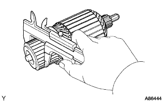 |
Using a dial indicator, measure the commutator's runout.
- Maximum commutator's runout:
- 0.05 mm (0.0020 in.)
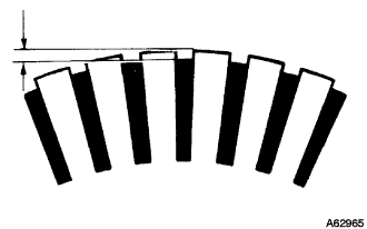
Check that the undercut depth is clean and free of foreign materials. Smooth out the edge.
- Standard undercut depth:
- 0.6 mm (0.024 in.)
- Minimum undercut depth:
- 0.2 mm (0.008 in.)
 |
| 3. INSPECT STARTER YOKE ASSEMBLY |
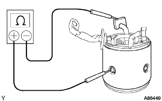
Inspect the resistance of the field coil.
Using an ohmmeter, measure the resistance between the lead wire and brush lead.
- Standard resistance:
Tester Connection Condition Specified Condition Lead wire - Brush lead - Below 1 Ω
Using an ohmmeter, measure the resistance between the brush lead and body.
- Standard resistance:
Tester Connection Condition Specified Condition Brush lead - Body - 10 kΩ or higher

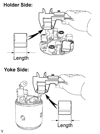
| 4. INSPECT BRUSH |
Using vernier calipers, measure the brush length.
- Standard length:
- 15.5 mm (0.610 in.)
- Minimum length:
- 10.0 mm (0.394 in.)
 |
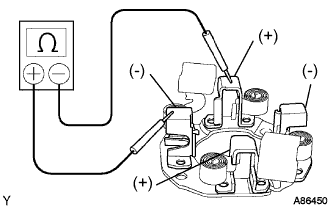
| 5. INSPECT STARTER BRUSH HOLDER ASSEMBLY |
Inspect the resistance.
Using an ohmmeter, measure the resistance between the positive (+) and negative (-) brush holders.
- Standard resistance:
Tester Connection Condition Specified Condition Positive brush holder - Negative brush holder - 10 kΩ or higher
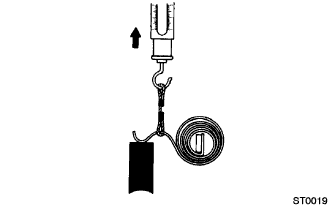
Inspect the load of the brush spring.
Take the pull scale reading immediately after the brush spring separates from the brush.
- Standard spring installed load:
- 23.5 to 29.5 N (2.4 to 3.0 kgf, 5.3 to 6.6 lbf)
| 6. INSPECT STARTER CENTER BEARING CLUTCH SUB-ASSEMBLY |
Check the gear teeth of the planetary gear and starter center bearing clutch for wear or damage.
If any planetary gear is damaged, replace the planetary gear assembly.
If any gear of the starter center bearing clutch is damaged, replace the clutch.
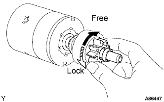
Check the movement of the clutch pinion gear.
Rotate the clutch pinion gear clockwise and check that it turns freely.
Try to rotate the clutch pinion gear counterclockwise and check that it locks.
If the clutch pinion gear cannot be turned clockwise smoothly, or does not lock in the counterclockwise direction, replace the starter clutch.
 |
| 7. INSPECT STARTER MAGNETIC SWITCH ASSEMBLY |
Inspect the resistance of the pull-in coil.
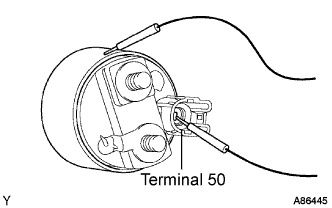
Using an ohmmeter, measure the resistance between terminals 50 and C.
- Standard resistance:
Tester Connection Condition Specified Condition Terminal 50 - Terminal C - Below 1 Ω
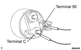
Inspect the resistance of the hold-in coil.
Using an ohmmeter, measure the resistance between terminal 50 and the switch body.
- Standard resistance:
Tester Connection Condition Specified Condition Terminal 50 - Switch body - Below 1.5 Ω