Выходной Вал Повторная Сборка. Corolla ZZE150
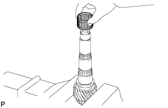
INSTALL NEEDLE ROLLER BEARING
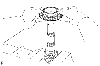
INSTALL REVERSE DRIVEN GEAR
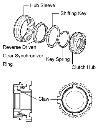
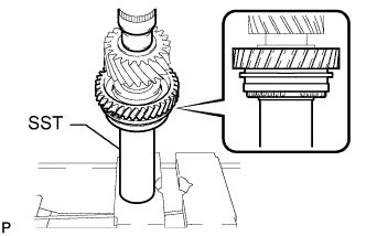
INSTALL NO. 4 TRANSMISSION CLUTCH HUB
INSTALL SHAFT SNAP RING
INSPECT REVERSE DRIVEN GEAR THRUST CLEARANCE
INSPECT REVERSE DRIVEN GEAR RADIAL CLEARANCE
INSTALL 5TH DRIVEN GEAR
INSTALL NO. 3 TRANSMISSION CLUTCH HUB
INSTALL SHAFT SNAP RING
INSPECT 5TH DRIVEN GEAR THRUST CLEARANCE
INSPECT 5TH DRIVEN GEAR RADIAL CLEARANCE
INSTALL 6TH DRIVEN GEAR
INSTALL NO. 2 OUTPUT SHAFT REAR BEARING
INSTALL NO. 2 OUTPUT SHAFT BEARING SNAP RING
INSPECT 6TH DRIVEN GEAR THRUST CLEARANCE
INSPECT 6TH DRIVEN GEAR RADIAL CLEARANCE
INSTALL NO. 2 OUTPUT SHAFT FRONT BEARING
INSTALL OUTPUT SHAFT FRONT BEARING INNER RACE
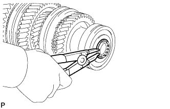
INSTALL OUTPUT SHAFT FRONT BEARING SHAFT SNAP RING
INSTALL 1ST DRIVEN GEAR
INSTALL NO. 1 TRANSMISSION CLUTCH HUB
INSTALL 2ND DRIVEN GEAR SYNCHRONIZER RING SET
INSTALL SYNCHROMESH SHIFTING KEY BALL
INSTALL NEEDLE ROLLER BEARING
INSTALL 2ND DRIVEN GEAR
INSTALL 2ND DRIVEN GEAR BEARING INNER RACE
INSTALL OUTPUT SHAFT BEARING SHAFT SNAP RING
INSPECT 1ST DRIVEN GEAR THRUST CLEARANCE
INSPECT 1ST DRIVEN GEAR RADIAL CLEARANCE
INSPECT 2ND DRIVEN GEAR THRUST CLEARANCE
INSPECT 2ND DRIVEN GEAR RADIAL CLEARANCE
INSTALL 4TH DRIVEN GEAR
INSTALL NO. 2 TRANSMISSION CLUTCH HUB
INSTALL SHAFT SNAP RING
INSPECT 4TH DRIVEN GEAR THRUST CLEARANCE
INSPECT 4TH DRIVEN GEAR RADIAL CLEARANCE
INSTALL 3RD DRIVEN GEAR
INSTALL OUTPUT SHAFT REAR BEARING
INSTALL OUTPUT SHAFT BEARING SHAFT SNAP RING
INSPECT 3RD DRIVEN GEAR THRUST CLEARANCE
INSPECT 3RD DRIVEN GEAR RADIAL CLEARANCE
Выходной Вал -- Повторная Сборка |
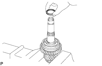
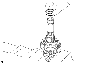
| 1. INSTALL NEEDLE ROLLER BEARING |
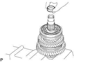
Coat the needle roller bearing with gear oil and install it to the No. 2 output shaft.
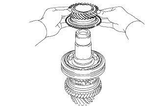
| 2. INSTALL REVERSE DRIVEN GEAR |
Coat the reverse driven gear with gear oil and install it to the No. 2 output shaft.
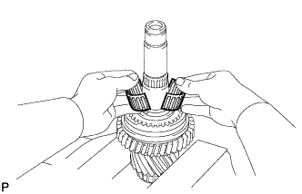
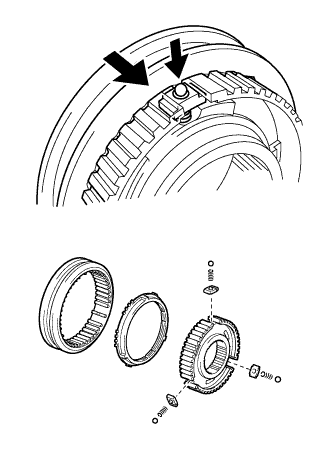
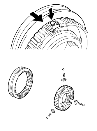
| 3. INSTALL NO. 4 TRANSMISSION CLUTCH HUB |
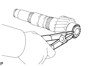
Install the key spring and 2 shifting keys to the clutch hub.
- УКАЗАНИЕ:
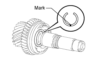
- Install the shifting keys with the grooves on the clutch hub side.
- Install the key spring with the claw on the clutch hub side.
- Refer to the illustration when installing the key spring and shifting keys.
Install the hub sleeve to the reverse driven gear as shown in the illustration.
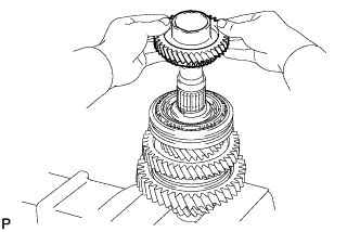
Coat the No. 4 transmission clutch hub with gear oil and install it to the No. 2 output shaft.
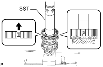
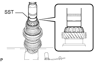
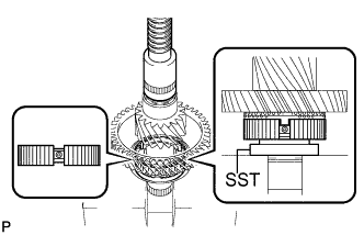
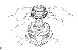
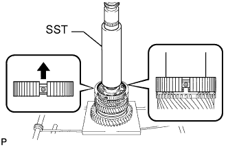
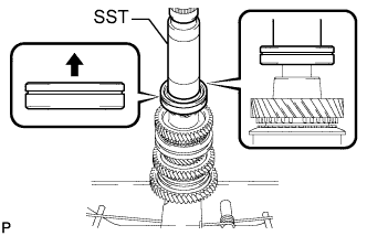
Using SST and a press, install the reverse gear and No. 4 transmission clutch hub to the No. 2 output shaft.
- SST
- 09308-14010
- ПРИМЕЧАНИЕ:
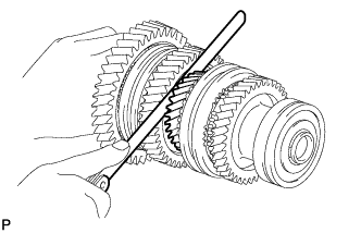
- After installation, make sure that the gear and synchronizer ring move smoothly.
- УКАЗАНИЕ:
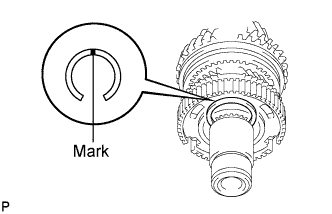
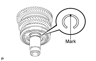
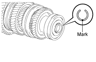
- Make sure that the protruding part on the synchronizer ring is fitted into the groove of the clutch hub.
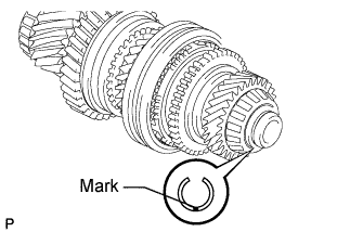
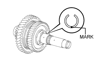
| 4. INSTALL SHAFT SNAP RING |
Select a new snap ring, using the table below, that makes the thrust clearance of the No. 4 transmission clutch hub less than 0.1 mm (0.0039 in.).
Mark
| Thickness mm (in.)
| Mark
| Thickness mm (in.)
|
A
| 2.25 to 2.30 (0.0886 to 0.0906)
| E
| 2.45 to 2.50 (0.0965 to 0.0984)
|
B
| 2.30 to 2.35 (0.0906 to 0.0925)
| F
| 2.50 to 2.55 (0.0984 to 0.1004)
|
C
| 2.35 to 2.40 (0.0925 to 0.0945)
| G
| 2.55 to 2.60 (0.1004 to 0.1024)
|
D
| 2.40 to 2.45 (0.0945 to 0.0965)
| H
| 2.60 to 2.65 (0.1024 to 0.1043)
|
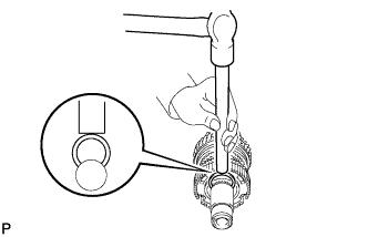
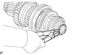
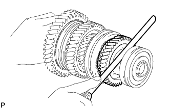
Using a brass bar and hammer, tap the snap ring onto the No. 2 output shaft.
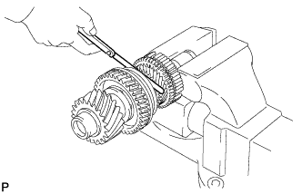
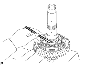
| 5. INSPECT REVERSE DRIVEN GEAR THRUST CLEARANCE |
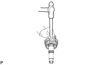
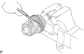
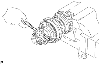
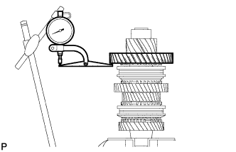
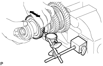
Using a feeler gauge, measure the reverse driven gear thrust clearance.
- Standard clearance:
- 0.11 to 0.34 mm (0.0043 to 0.0134 in.)
- Maximum clearance:
- 0.34 mm (0.0134 in.)
If the clearance exceeds the maximum, replace the reverse driven gear, needle roller bearing, or shaft.
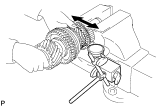
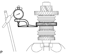
| 6. INSPECT REVERSE DRIVEN GEAR RADIAL CLEARANCE |
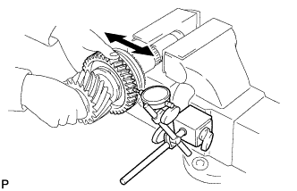
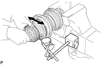
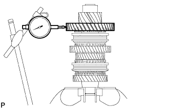
Using a dial indicator, measure the reverse driven gear radial clearance.
- Standard clearance:
- 0.015 to 0.068 mm (0.0006 to 0.0027 in.)
- Maximum clearance:
- 0.068 mm (0.0027 in.)
If the clearance exceeds the maximum, replace the reverse driven gear, needle roller bearing, or shaft.
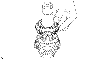
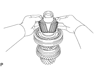
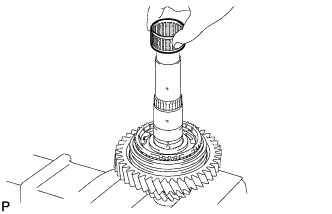
| 7. INSTALL 5TH DRIVEN GEAR |
Install the output shaft spacer to the No. 2 output shaft.
Coat the needle roller bearing with gear oil and install it to the No. 2 output shaft.
Install the output shaft spacer to the No. 2 output shaft.
Coat the 5th driven gear with gear oil and install it to the No. 2 output shaft.
| 8. INSTALL NO. 3 TRANSMISSION CLUTCH HUB |
Apply gear oil to the sleeve and hub.
Install the clutch hub sleeve to the clutch hub.
Install the 3 shifting keys to the clutch hub.
Install the 3 shifting key springs to the clutch hub.
Place the balls in the holes of the shifting keys and install the hub sleeve while pushing in the balls.
- ПРИМЕЧАНИЕ:
- Take care to prevent the balls from scattering.
Coat the 5th driven gear synchronizer ring with gear oil and install them to the 5th driven gear.
Using SST and a press, install the No. 3 transmission clutch hub to the No. 2 output shaft.
- SST
- 09308-14010
- ПРИМЕЧАНИЕ:
- After installation, make sure that the gear and synchronizer ring move smoothly.
- УКАЗАНИЕ:
- Make sure that the protruding part on the synchronizer ring is fitted into the groove of the clutch hub.
| 9. INSTALL SHAFT SNAP RING |
Select a new snap ring, using the table below, that makes the thrust clearance of the No. 3 transmission clutch hub less than 0.1 mm (0.0039 in.).
Mark
| Thickness mm (in.)
| Mark
| Thickness mm (in.)
|
1
| 2.25 to 2.30 (0.0886 to 0.0906)
| 4
| 2.40 to 2.45 (0.0945 to 0.0965)
|
2
| 2.30 to 2.35 (0.0906 to 0.0925)
| 5
| 2.45 to 2.50 (0.0965 to 0.0984)
|
3
| 2.35 to 2.40 (0.0925 to 0.0945)
| 6
| 2.50 to 2.55 (0.0984 to 0.1004)
|
Using a brass bar and hammer, tap the snap ring onto the No. 2 output shaft.
| 10. INSPECT 5TH DRIVEN GEAR THRUST CLEARANCE |
Using a feeler gauge, measure the 5th driven gear thrust clearance.
- Standard clearance:
- 0.10 to 0.55 mm (0.0039 to 0.0217 in.)
- Maximum clearance:
- 0.55 mm (0.0217 in.)
| 11. INSPECT 5TH DRIVEN GEAR RADIAL CLEARANCE |
Using a dial indicator, measure the 5th driven gear radial clearance.
- Standard clearance:
- 0.015 to 0.066 mm (0.0006 to 0.0026 in.)
- Maximum clearance:
- 0.066 mm (0.0026 in.)
If the clearance exceeds the maximum, replace the 5th driven gear, needle roller bearing, or shaft.
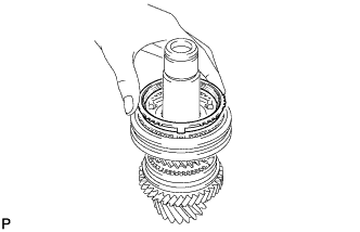
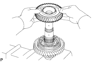
| 12. INSTALL 6TH DRIVEN GEAR |
Install the output shaft spacer to the No. 2 output shaft.
Coat the needle roller bearing with gear oil and install it to the No. 2 output shaft.
Coat the synchronizer ring with gear oil and install it to the transmission clutch hub.
Coat the 6th driven gear with gear oil and install it to the No. 2 output shaft.
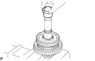
| 13. INSTALL NO. 2 OUTPUT SHAFT REAR BEARING |
Using SST and a press, install the No. 2 output shaft rear bearing to the No. 2 output shaft.
- SST
- 09710-04071
- ПРИМЕЧАНИЕ:
- After installation, make sure that the gear and synchronizer ring move smoothly.
| 14. INSTALL NO. 2 OUTPUT SHAFT BEARING SNAP RING |
Select a new snap ring, using the table below, that makes the thrust clearance of the 6th gear less than 0.1 mm (0.0039 in.).
Mark
| Thickness mm (in.)
| Mark
| Thickness mm (in.)
|
B
| 1.85 to 1.90 (0.0728 to 0.0748)
| 0
| 2.05 to 2.10 (0.0807 to 0.0827)
|
C
| 1.90 to 1.95 (0.0748 to 0.0768)
| 1
| 2.10 to 2.15 (0.0827 to 0.0846)
|
D
| 1.95 to 2.00 (0.0768 to 0.0787)
| 2
| 2.15 to 2.20 (0.0846 to 0.0866)
|
E
| 2.00 to 2.05 (0.0787 to 0.0807)
| -
| -
|
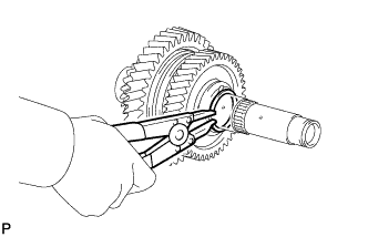
Using a snap ring expander, install the snap ring onto the No. 2 output shaft.
| 15. INSPECT 6TH DRIVEN GEAR THRUST CLEARANCE |
Using a feeler gauge, measure the 6th driven gear thrust clearance.
- Standard clearance:
- 0.10 to 0.55 mm (0.0039 to 0.0217 in.)
- Maximum clearance:
- 0.55 mm (0.0217 in.)
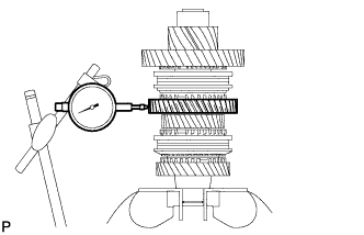
| 16. INSPECT 6TH DRIVEN GEAR RADIAL CLEARANCE |
Using a dial indicator, measure the 6th driven gear radial clearance.
- Standard clearance:
- 0.015 to 0.066 mm (0.0006 to 0.0026 in.)
- Maximum clearance:
- 0.066 mm (0.0026 in.)
If the clearance exceeds the maximum, replace the 6th driven gear, needle roller bearing, or shaft.
| 17. INSTALL NO. 2 OUTPUT SHAFT FRONT BEARING |
Using SST and a press, install the No. 2 output shaft front bearing to the No. 2 output shaft.
- SST
- 09309-37010
09506-30012
| 18. INSTALL OUTPUT SHAFT FRONT BEARING INNER RACE |
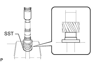
Using SST and a press, install the output shaft front bearing inner race to the No. 1 output shaft.
- SST
- 09309-14040
| 19. INSTALL OUTPUT SHAFT FRONT BEARING SHAFT SNAP RING |
Using a snap ring expander, install a new snap ring to the No. 1 output shaft.
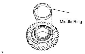
| 20. INSTALL 1ST DRIVEN GEAR |
Coat the needle roller bearing with gear oil and install it to the No. 1 output shaft.
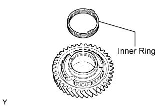
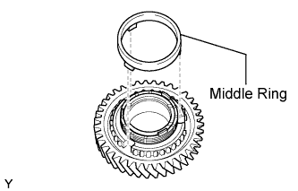
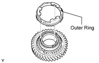
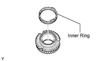
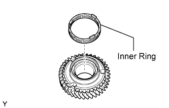
Install the inner ring onto the 1st driven gear.
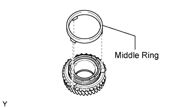
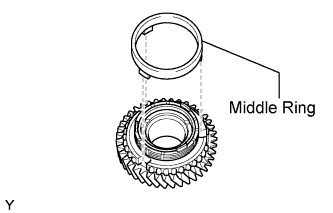
Install the middle ring onto the 1st driven gear.
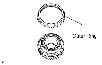
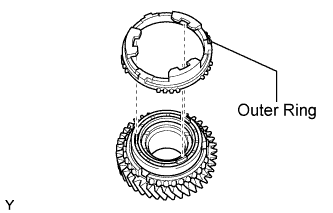
Install the outer ring onto the 1st driven gear.
Coat the 1st driven gear with gear oil and install it to the No. 1 output shaft.
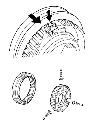
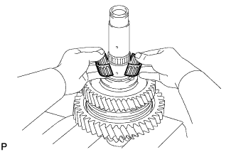
| 21. INSTALL NO. 1 TRANSMISSION CLUTCH HUB |
Apply gear oil to the sleeve and hub.
Install the clutch hub sleeve to the clutch hub.
Install the 3 shifting keys to the clutch hub.
Install the 3 shifting key springs to the clutch hub.
Place the balls in the holes of the shifting keys and install the hub sleeve while pushing in the balls.
- ПРИМЕЧАНИЕ:
- Take care to prevent the balls from scattering.
Coat the 1st driven gear synchronizer ring set with gear oil.
Using SST and a press, install the No. 1 transmission hub sleeve to the No. 1 output shaft.
- SST
- 09726-40010
- ПРИМЕЧАНИЕ:
- After installation, make sure that the gear and synchronizer ring move smoothly.
- УКАЗАНИЕ:
- Make sure that the protruding part on the synchronizer ring is fitted into the groove of the clutch hub.
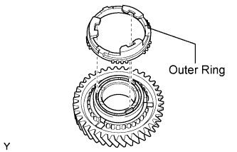
| 22. INSTALL 2ND DRIVEN GEAR SYNCHRONIZER RING SET |
Coat the 2nd driven gear synchronizer ring set with gear oil.
Install the outer ring onto the 2nd driven gear.
Install the middle ring onto the 2nd driven gear.
Install the inner ring onto the 2nd driven gear.
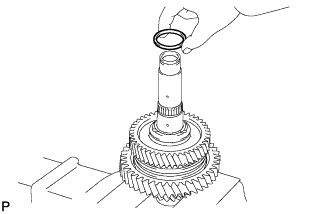
| 23. INSTALL SYNCHROMESH SHIFTING KEY BALL |
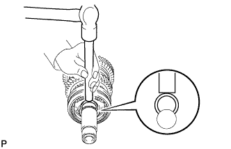
Install the key ball onto the No. 1 output shaft.
| 24. INSTALL NEEDLE ROLLER BEARING |
Coat the needle roller bearing with gear oil and install it to the No. 1 output shaft.
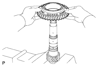
| 25. INSTALL 2ND DRIVEN GEAR |
Coat the 2nd driven gear with gear oil and install it to the No. 1 output shaft.
| 26. INSTALL 2ND DRIVEN GEAR BEARING INNER RACE |
Align the groove of the 2nd driven gear bearing inner race with the ball and install the inner race.
| 27. INSTALL OUTPUT SHAFT BEARING SHAFT SNAP RING |
Select a new snap ring, using the table below, that makes the thrust clearance of the 2nd gear less than 0.1 mm (0.0039 in.).
Mark
| Thickness mm (in.)
| Mark
| Thickness mm (in.)
|
A
| 2.25 to 2.30 (0.0886 to 0.0906)
| E
| 2.45 to 2.50 (0.0965 to 0.0984)
|
B
| 2.30 to 2.35 (0.0906 to 0.0925)
| F
| 2.50 to 2.55 (0.0984 to 0.1004)
|
C
| 2.35 to 2.40 (0.0925 to 0.0945)
| G
| 2.55 to 2.60 (0.1004 to 0.1024)
|
D
| 2.40 to 2.45 (0.0945 to 0.0965)
| H
| 2.60 to 2.65 (0.1024 to 0.1043)
|
Using a snap ring expander, install the snap ring to the No. 1 output shaft.
- УКАЗАНИЕ:
- Do not damage the journal surface of the No. 1 output shaft.
| 28. INSPECT 1ST DRIVEN GEAR THRUST CLEARANCE |
Using a dial indicator, measure the 1st driven gear thrust clearance.
- Standard clearance:
- 0.10 to 0.35 mm (0.0039 to 0.0138 in.)
- Maximum clearance:
- 0.35 mm (0.0138 in.)
| 29. INSPECT 1ST DRIVEN GEAR RADIAL CLEARANCE |
Using a dial indicator, measure the 1st driven gear radial clearance.
- Standard clearance:
- 0.015 to 0.068 mm (0.0006 to 0.0027 in.)
- Maximum clearance:
- 0.068 mm (0.0027 in.)
If the clearance exceeds the maximum, replace the 1st driven gear, needle roller bearing, or shaft.
| 30. INSPECT 2ND DRIVEN GEAR THRUST CLEARANCE |
Using a dial indicator, measure the 2nd driven gear thrust clearance.
- Standard clearance:
- 0.11 to 0.46 mm (0.0043 to 0.0181 in.)
- Maximum clearance:
- 0.46 mm (0.0181 in.)
| 31. INSPECT 2ND DRIVEN GEAR RADIAL CLEARANCE |
Using a dial indicator, measure the 2nd driven gear radial clearance.
- Standard clearance:
- 0.015 to 0.048 mm (0.0006 to 0.0019 in.)
- Maximum clearance:
- 0.048 mm (0.0019 in.)
If the clearance exceeds the maximum, replace the 2nd driven gear, needle roller bearing, or shaft.
| 32. INSTALL 4TH DRIVEN GEAR |
Install the output shaft spacer to the No. 1 output shaft.
Coat the 4th driven gear needle roller bearing with gear oil and install it to the No. 1 output shaft.
Install the inner ring onto the 4th driven gear.
Install the middle ring onto the 4th driven gear.
Install the outer ring onto the 4th driven gear.
Coat the 4th driven gear with gear oil and install it to the No. 1 output shaft.
| 33. INSTALL NO. 2 TRANSMISSION CLUTCH HUB |
Apply gear oil to the sleeve and hub.
Install the clutch hub sleeve to the clutch hub.
Install the 3 shifting keys to the clutch hub.
Install the 3 shifting key springs to the clutch hub.
Place the balls in the holes of the shifting keys and install the hub sleeve while pushing in the balls.
- ПРИМЕЧАНИЕ:
- Take care to prevent the balls from scattering.
Coat the 4th driven gear synchronizer ring set with gear oil.
Using SST and a press, install the No. 1 transmission clutch hub to the 4th driven gear.
- SST
- 09309-14010
- ПРИМЕЧАНИЕ:
- After installation, make sure that the gear and synchronizer ring move smoothly.
- УКАЗАНИЕ:
- Make sure that the protruding part on the synchronizer ring is fitted into the groove of the clutch hub.
| 34. INSTALL SHAFT SNAP RING |
Select a new snap ring, using the table below, that makes the thrust clearance of the No. 2 transmission clutch hub less than 0.1 mm (0.0039 in.).
Mark
| Thickness mm (in.)
| Mark
| Thickness mm (in.)
|
1
| 2.25 to 2.30 (0.0886 to 0.0906)
| 4
| 2.40 to 2.45 (0.0945 to 0.0965)
|
2
| 2.30 to 2.35 (0.0906 to 0.0925)
| 5
| 2.45 to 2.50 (0.0965 to 0.0984)
|
3
| 2.35 to 2.40 (0.0925 to 0.0945)
| 6
| 2.50 to 2.55 (0.0984 to 0.1004)
|
Using a brass bar and hammer, tap the snap ring to the No. 1 output shaft.
| 35. INSPECT 4TH DRIVEN GEAR THRUST CLEARANCE |
Using a feeler gauge, measure the 4th driven gear thrust clearance.
- Standard clearance:
- 0.10 to 0.65 mm (0.0039 to 0.0256 in.)
- Maximum clearance:
- 0.65 mm (0.0256 in.)
| 36. INSPECT 4TH DRIVEN GEAR RADIAL CLEARANCE |
Using a dial indicator, measure the 4th driven gear radial clearance.
- Standard clearance:
- 0.015 to 0.066 mm (0.0006 to 0.0026 in.)
- Maximum clearance:
- 0.066 mm (0.0026 in.)
If the clearance exceeds the maximum, replace the 4th driven gear, needle roller bearing, or shaft.
| 37. INSTALL 3RD DRIVEN GEAR |
Coat the 3rd driven gear synchronizer ring set with gear oil.
Install the inner ring onto the 3rd driven gear.
Install the middle ring onto the 3rd driven gear.
Install the outer ring onto the 3rd driven gear.
Coat the needle roller bearing with gear oil and install it to the No. 1 output shaft.
Install the output shaft spacer to the No. 1 output shaft.
Coat the 3rd driven gear with gear oil and install it to the No. 1 output shaft.
| 38. INSTALL OUTPUT SHAFT REAR BEARING |
Using SST and a press, install the output shaft rear bearing to the No. 1 output shaft.
- SST
- 09308-14010
- ПРИМЕЧАНИЕ:
- After installation, make sure that the gear and synchronizer ring move smoothly.
- УКАЗАНИЕ:
- When pressing in the bearing, apply force only to the inner race. Do not apply force to the seal.
| 39. INSTALL OUTPUT SHAFT BEARING SHAFT SNAP RING |
Select a new snap ring, using the table below, that makes the thrust clearance of the output shaft bearing less than 0.1 mm (0.0039 in.).
Mark
| Thickness mm (in.)
| Mark
| Thickness mm (in.)
|
B
| 1.85 to 1.90 (0.0728 to 0.0748)
| 0
| 2.05 to 2.10 (0.0807 to 0.0827)
|
C
| 1.90 to 1.95 (0.0748 to 0.0768)
| 1
| 2.10 to 2.15 (0.0827 to 0.0846)
|
D
| 1.95 to 2.00 (0.0768 to 0.0787)
| 2
| 2.15 to 2.20 (0.0846 to 0.0866)
|
E
| 2.00 to 2.05 (0.0787 to 0.0807)
| -
| -
|
Using a snap ring expander, install the snap ring onto the No. 1 output shaft.
| 40. INSPECT 3RD DRIVEN GEAR THRUST CLEARANCE |
Using a feeler gauge, measure the 3rd driven gear thrust clearance.
- Standard clearance:
- 0.11 to 0.54 mm (0.0043 to 0.0213 in.)
- Maximum clearance:
- 0.54 mm (0.0213 in.)
| 41. INSPECT 3RD DRIVEN GEAR RADIAL CLEARANCE |
Using a dial indicator, measure the 3rd driven gear radial clearance.
- Standard clearance:
- 0.015 to 0.066 mm (0.0006 to 0.0026 in.)
- Maximum clearance:
- 0.066 mm (0.0026 in.)
If the clearance exceeds the maximum, replace the 3rd driven gear, needle roller bearing, or shaft.