Выходной Вал Разборка. Corolla ZZE150
INSPECT 1ST DRIVEN GEAR THRUST CLEARANCE
INSPECT 1ST DRIVEN GEAR RADIAL CLEARANCE
INSPECT 2ND DRIVEN GEAR THRUST CLEARANCE
INSPECT 2ND DRIVEN GEAR RADIAL CLEARANCE
INSPECT 3RD DRIVEN GEAR THRUST CLEARANCE
INSPECT 3RD DRIVEN GEAR RADIAL CLEARANCE
INSPECT 4TH DRIVEN GEAR THRUST CLEARANCE
INSPECT 4TH DRIVEN GEAR RADIAL CLEARANCE
REMOVE OUTPUT SHAFT BEARING SHAFT SNAP RING
REMOVE OUTPUT SHAFT REAR BEARING
REMOVE 3RD DRIVEN GEAR
REMOVE SPACER
REMOVE NEEDLE ROLLER BEARING
REMOVE 3RD DRIVEN GEAR SYNCHRONIZER RING SET
REMOVE SHAFT SNAP RING
REMOVE 4TH DRIVEN GEAR
REMOVE 4TH DRIVEN GEAR SYNCHRONIZER RING SET
REMOVE NO. 2 TRANSMISSION CLUTCH HUB
REMOVE NEEDLE ROLLER BEARING
REMOVE SPACER
REMOVE OUTPUT SHAFT BEARING SHAFT SNAP RING
REMOVE 2ND DRIVEN GEAR BEARING INNER RACE
REMOVE 2ND DRIVEN GEAR
REMOVE NEEDLE ROLLER BEARING
REMOVE SYNCHROMESH SHIFTING KEY BALL
REMOVE 2ND DRIVEN GEAR SYNCHRONIZER RING SET
REMOVE 1ST DRIVEN GEAR
REMOVE 1ST DRIVEN GEAR SYNCHRONIZER RING SET
REMOVE NO. 1 TRANSMISSION CLUTCH HUB
REMOVE NEEDLE ROLLER BEARING
REMOVE OUTPUT SHAFT FRONT BEARING SHAFT SNAP RING
REMOVE OUTPUT SHAFT FRONT BEARING INNER RACE
INSPECT 5TH DRIVEN GEAR THRUST CLEARANCE
INSPECT 5TH DRIVEN GEAR RADIAL CLEARANCE
INSPECT 6TH DRIVEN GEAR THRUST CLEARANCE
INSPECT 6TH DRIVEN GEAR RADIAL CLEARANCE
INSPECT REVERSE DRIVEN GEAR THRUST CLEARANCE
INSPECT REVERSE DRIVEN GEAR RADIAL CLEARANCE
REMOVE NO. 2 OUTPUT SHAFT BEARING SNAP RING
REMOVE NO. 2 OUTPUT SHAFT REAR BEARING
REMOVE 6TH GEAR NEEDLE ROLLER BEARING
REMOVE SPACER
REMOVE 6TH DRIVEN GEAR SYNCHRONIZER RING
REMOVE SHAFT SNAP RING
REMOVE 5TH DRIVEN GEAR
REMOVE 5TH DRIVEN GEAR SYNCHRONIZER RING
REMOVE NO. 3 TRANSMISSION CLUTCH HUB
REMOVE SHAFT SNAP RING
REMOVE REVERSE DRIVEN GEAR
REMOVE REVERSE DRIVEN GEAR SYNCHRONIZER RING
REMOVE NO. 4 TRANSMISSION CLUTCH HUB
REMOVE 3RD GEAR NEEDLE ROLLER BEARING
REMOVE NO. 2 OUTPUT SHAFT FRONT BEARING
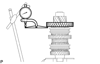
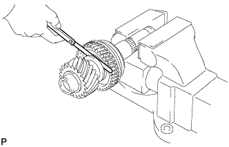
| 1. INSPECT 1ST DRIVEN GEAR THRUST CLEARANCE |
Using a dial indicator, measure the 1st driven gear thrust clearance.
- Standard clearance:
- 0.10 to 0.35 mm (0.0039 to 0.0138 in.)
- Maximum clearance:
- 0.35 mm (0.0138 in.)
If the clearance exceeds the maximum, replace the 1st driven gear, needle roller bearing, or shaft.
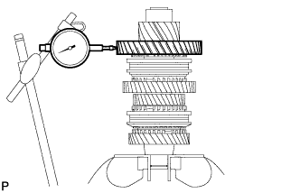
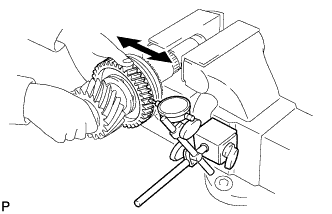
| 2. INSPECT 1ST DRIVEN GEAR RADIAL CLEARANCE |
Using a dial indicator, measure the 1st driven gear radial clearance.
- Standard clearance:
- 0.015 to 0.068 mm (0.0006 to 0.0027 in.)
- Maximum clearance:
- 0.068 mm (0.0027 in.)
If the clearance exceeds the maximum, replace the 1st driven gear, needle roller bearing, or shaft.
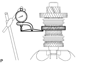
| 3. INSPECT 2ND DRIVEN GEAR THRUST CLEARANCE |
Using a dial indicator, measure the 2nd driven gear thrust clearance.
- Standard clearance:
- 0.11 to 0.46 mm (0.0043 to 0.018 in.)
- Maximum clearance:
- 0.46 mm (0.018 in.)
If the clearance exceeds the maximum, replace the 2nd driven gear, needle roller bearing, or shaft.
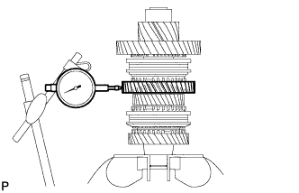
| 4. INSPECT 2ND DRIVEN GEAR RADIAL CLEARANCE |
Using a dial indicator, measure the 2nd driven gear radial clearance.
- Standard clearance:
- 0.015 to 0.048 mm (0.0006 to 0.0019 in.)
- Maximum clearance:
- 0.048 mm (0.0019 in.)
If the clearance exceeds the maximum, replace the 2nd driven gear, needle roller bearing, or shaft.
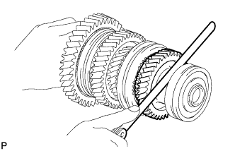
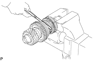
| 5. INSPECT 3RD DRIVEN GEAR THRUST CLEARANCE |
Using a feeler gauge, measure the 3rd driven gear thrust clearance.
- Standard clearance:
- 0.11 to 0.54 mm (0.0043 to 0.0213 in.)
- Maximum clearance:
- 0.54 mm (0.0213 in.)
If the clearance exceeds the maximum, replace the 3rd driven gear, needle roller bearing, or shaft.
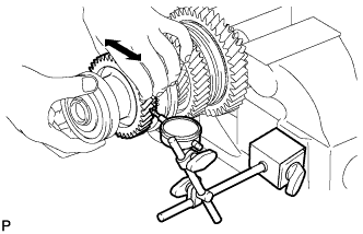
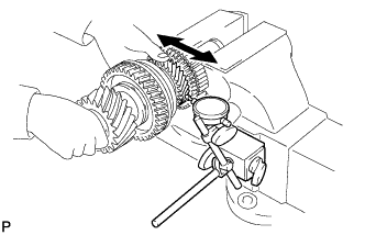
| 6. INSPECT 3RD DRIVEN GEAR RADIAL CLEARANCE |
Using a dial indicator, measure the 3rd driven gear radial clearance.
- Standard clearance:
- 0.015 to 0.066 mm (0.0006 to 0.0026 in.)
- Maximum clearance:
- 0.066 mm (0.0026 in.)
If the clearance exceeds the maximum, replace the 3rd driven gear, needle roller bearing, or shaft.
- ПРИМЕЧАНИЕ:
- Support both ends of the output shaft at all times when the output shaft is mounted in a horizontal position. Failure to support both ends of the shaft will result in the shaft falling out of the vise.
- Only secure the output shaft in a vice which has soft jaws. Failure to use caution when mounting or working on the output shaft can result in damage to bearings, bearing surfaces or damage to gear teeth.
- УКАЗАНИЕ:
- Make sure that the output shaft is mounted rigidly when measuring the radial clearance. If the output shaft moves, the measurement will be inaccurate.
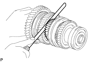
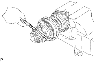
| 7. INSPECT 4TH DRIVEN GEAR THRUST CLEARANCE |
Using a feeler gauge, measure the 4th driven gear thrust clearance.
- Standard clearance:
- 0.10 to 0.65 mm (0.0039 to 0.0256 in.)
- Maximum clearance:
- 0.65 mm (0.0256 in.)
If the clearance exceeds the maximum, replace the 4th driven gear, needle roller bearing, or shaft.
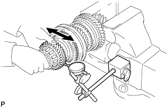
| 8. INSPECT 4TH DRIVEN GEAR RADIAL CLEARANCE |
Using a dial indicator, measure the 4th driven gear radial clearance.
- Standard clearance:
- 0.015 to 0.066 mm (0.0006 to 0.0026 in.)
- Maximum clearance:
- 0.066 mm (0.0026 in.)
If the clearance exceeds the maximum, replace the 4th driven gear, needle roller bearing, or shaft.
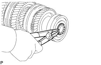
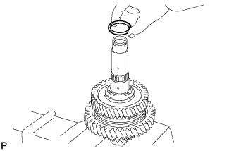
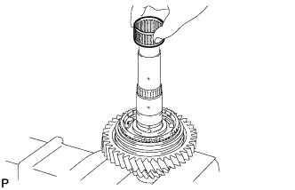
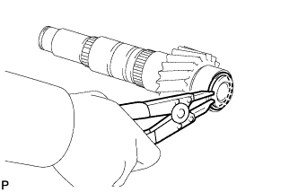
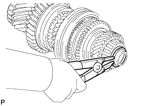
| 9. REMOVE OUTPUT SHAFT BEARING SHAFT SNAP RING |
Using a snap ring expander, remove the output shaft bearing shaft snap ring from the No. 1 output shaft.
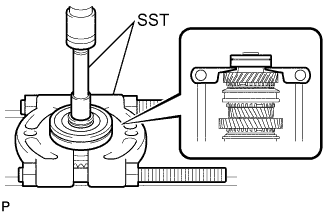
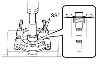
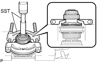
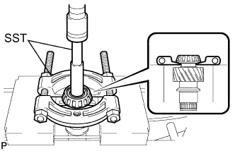
| 10. REMOVE OUTPUT SHAFT REAR BEARING |
Using SST and a press, remove the output shaft rear bearing from the No. 1 output shaft.
- SST
- 09201-31010
09950-00020
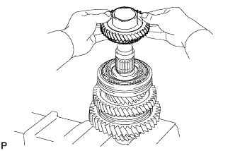
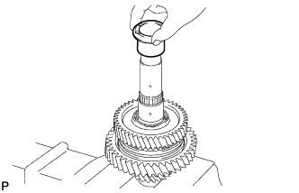
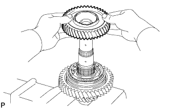
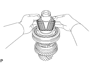
| 11. REMOVE 3RD DRIVEN GEAR |
Remove the 3rd driven gear from the No. 1 output shaft.
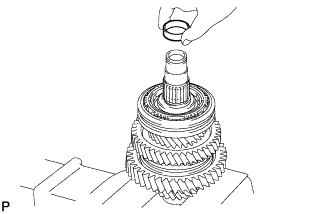
Remove the spacer from the No. 1 output shaft.
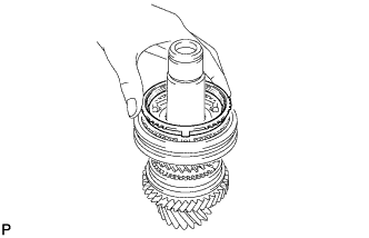
| 13. REMOVE NEEDLE ROLLER BEARING |
Remove the needle roller bearing from the No. 1 output shaft.
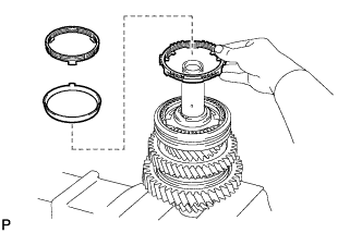
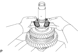
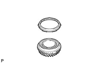
| 14. REMOVE 3RD DRIVEN GEAR SYNCHRONIZER RING SET |
Remove the synchronizer ring set from the No. 1 output shaft.
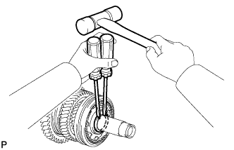
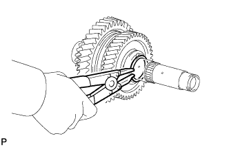
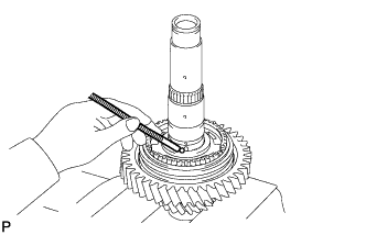
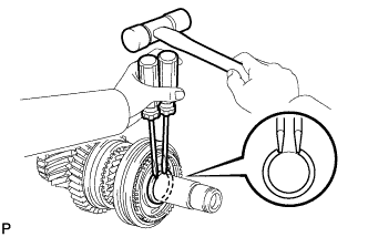
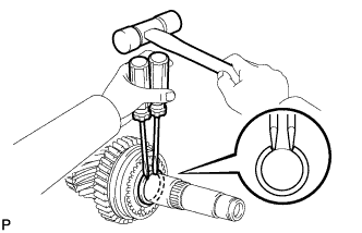
| 15. REMOVE SHAFT SNAP RING |
Using 2 screwdrivers and a hammer, remove the shaft snap ring from the No. 1 output shaft.
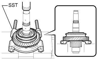
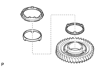
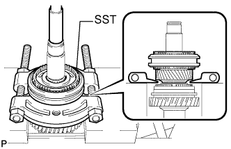
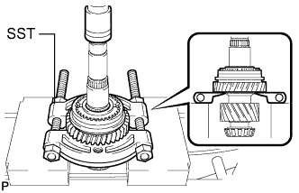
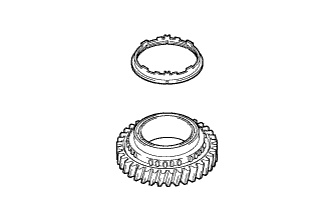
| 16. REMOVE 4TH DRIVEN GEAR |
Using SST and a press, remove the No. 2 transmission hub sleeve, 4th driven gear synchronizer ring set, and 4th driven gear from the No. 1 output shaft.
- SST
- 09950-00020
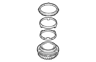
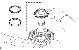
| 17. REMOVE 4TH DRIVEN GEAR SYNCHRONIZER RING SET |
Remove the 4th driven gear synchronizer ring set from the 4th driven gear.
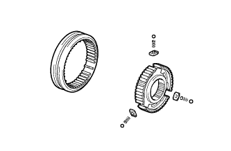
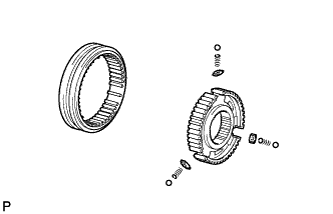
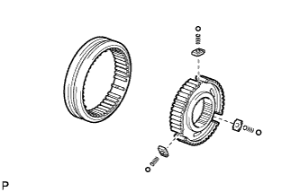
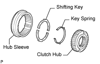
| 18. REMOVE NO. 2 TRANSMISSION CLUTCH HUB |
Remove the clutch hub, 3 keys, 3 balls, and 3 key springs from the hub sleeve.
- ПРИМЕЧАНИЕ:
- Pay attention to prevent the balls and springs from scattering.
| 19. REMOVE NEEDLE ROLLER BEARING |
Remove the needle roller bearing from the No. 1 output shaft.
Remove the spacer from the No. 1 output shaft.
| 21. REMOVE OUTPUT SHAFT BEARING SHAFT SNAP RING |
Using a snap ring expander, remove the output shaft bearing shaft snap ring from the No. 1 output shaft.
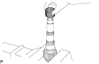
| 22. REMOVE 2ND DRIVEN GEAR BEARING INNER RACE |
Remove the 2nd gear bearing inner race from the No. 1 output shaft.
| 23. REMOVE 2ND DRIVEN GEAR |
Remove the 2nd driven gear from the No. 1 output shaft.
| 24. REMOVE NEEDLE ROLLER BEARING |
Remove the needle roller bearing from the No. 1 output shaft.
| 25. REMOVE SYNCHROMESH SHIFTING KEY BALL |
Remove the synchromesh shifting key ball from the No. 1 output shaft.
| 26. REMOVE 2ND DRIVEN GEAR SYNCHRONIZER RING SET |
Remove the synchronizer ring set from the No. 1 output shaft.
| 27. REMOVE 1ST DRIVEN GEAR |
Using SST and a press, remove the No. 1 transmission clutch hub and sleeve, 1st driven gear synchronizer ring set, and 1st driven gear from the No. 1 output shaft.
- SST
- 09950-00020
- ПРИМЕЧАНИЕ:
- Make sure that the synchromesh shifting key ball has been removed before using the press.
| 28. REMOVE 1ST DRIVEN GEAR SYNCHRONIZER RING SET |
Remove the synchronizer ring set from the 1st driven gear.
| 29. REMOVE NO. 1 TRANSMISSION CLUTCH HUB |
Remove the clutch hub, 3 keys, 3 balls, and 3 key springs from the hub sleeve.
- ПРИМЕЧАНИЕ:
- Pay attention to prevent the balls and springs from scattering.
| 30. REMOVE NEEDLE ROLLER BEARING |
Remove the needle roller bearing from the No. 1 output shaft.
| 31. REMOVE OUTPUT SHAFT FRONT BEARING SHAFT SNAP RING |
Using a snap ring expander, remove the output shaft front bearing shaft snap ring from the No. 1 output shaft.
| 32. REMOVE OUTPUT SHAFT FRONT BEARING INNER RACE |
Using SST and a press, remove the output shaft front bearing inner race from the No. 1 output shaft.
- SST
- 09201-31010
09950-00020
| 33. INSPECT 5TH DRIVEN GEAR THRUST CLEARANCE |
Using a feeler gauge, measure the 5th driven gear thrust clearance.
- Standard clearance:
- 0.10 to 0.55 mm (0.0039 to 0.0217 in.)
- Maximum clearance:
- 0.55 mm (0.0217 in.)
If the clearance exceeds the maximum, replace the 5th driven gear, needle roller bearing, or shaft.
- ПРИМЕЧАНИЕ:
- Only secure the output shaft in a vice which has soft jaws. Failure to use caution when mounting or working on the output shaft can result in damage to bearings, bearing surfaces or damage to gear teeth.
- Use caution when working with an output shaft secured in a vise. The output shaft is heavy, and may be knocked from the vise easily.
| 34. INSPECT 5TH DRIVEN GEAR RADIAL CLEARANCE |
Using a dial indicator, measure the 5th driven gear radial clearance.
- Standard clearance:
- 0.015 to 0.066 mm (0.0006 to 0.0026 in.)
- Maximum clearance:
- 0.066 mm (0.0026 in.)
If the clearance exceeds the maximum, replace the 5th driven gear, needle roller bearing, or shaft.
- УКАЗАНИЕ:
- Make sure that the output shaft is mounted rigidly when measuring the radial clearance. If the output shaft moves, the measurement will be inaccurate.
| 35. INSPECT 6TH DRIVEN GEAR THRUST CLEARANCE |
Using a feeler gauge, measure the 6th driven gear thrust clearance.
- Standard clearance:
- 0.10 to 0.55 mm (0.0039 to 0.0217 in.)
- Maximum clearance:
- 0.55 mm (0.0217 in.)
If the clearance exceeds the maximum, replace the 6th driven gear, needle roller bearing, or shaft.
- ПРИМЕЧАНИЕ:
- Use caution when securing the output shaft in a vise. Use only a soft jawed vise. Use a shop rag or a piece of cloth to help protect the teeth of the gear. Do not overtighten the vise.
- Support both ends of the output shaft at all times when the output shaft is mounted in a horizontal position. Failure to support both ends of the shaft will result in the shaft falling out of the vise.
| 36. INSPECT 6TH DRIVEN GEAR RADIAL CLEARANCE |
Using a dial indicator, measure the 6th driven gear radial clearance.
- Standard clearance:
- 0.015 to 0.066 mm (0.0006 to 0.0026 in.)
- Maximum clearance:
- 0.066 mm (0.0026 in.)
If the clearance exceeds the maximum, replace the 6th driven gear, needle roller bearing, or shaft.
| 37. INSPECT REVERSE DRIVEN GEAR THRUST CLEARANCE |
Using a feeler gauge, measure the reverse driven gear thrust clearance.
- Standard clearance:
- 0.11 to 0.34 mm (0.0043 to 0.0134 in.)
- Maximum clearance:
- 0.34 mm (0.0134 in.)
If the clearance exceeds the maximum, replace the reverse driven gear, needle roller bearing, or shaft.
| 38. INSPECT REVERSE DRIVEN GEAR RADIAL CLEARANCE |
Using a dial indicator, measure the reverse driven gear radial clearance.
- Standard clearance:
- 0.015 to 0.068 mm (0.0006 to 0.0027 in.)
- Maximum clearance:
- 0.068 mm (0.0027 in.)
If the clearance exceeds the maximum, replace the reverse driven gear, needle roller bearing, or shaft.
- УКАЗАНИЕ:
- Make sure that the output shaft is mounted rigidly when measuring the radial clearance. If the output shaft moves, the measurement will be inaccurate.
| 39. REMOVE NO. 2 OUTPUT SHAFT BEARING SNAP RING |
Using a snap ring expander, remove the No. 2 output shaft bearing snap ring from the No. 2 output shaft.
| 40. REMOVE NO. 2 OUTPUT SHAFT REAR BEARING |
Using SST and a press, remove the No. 2 output shaft rear bearing and 6th driven gear from the No. 2 output shaft.
- SST
- 09201-31010
09950-00020
| 41. REMOVE 6TH GEAR NEEDLE ROLLER BEARING |
Remove the needle roller bearing from the No. 2 output shaft.
Remove the spacer from the No. 2 output shaft.
| 43. REMOVE 6TH DRIVEN GEAR SYNCHRONIZER RING |
Remove the 6th driven gear synchronizer ring from the No. 2 output shaft.
| 44. REMOVE SHAFT SNAP RING |
Using 2 screwdrivers and a hammer, remove the shaft snap ring from the No. 2 output shaft.
| 45. REMOVE 5TH DRIVEN GEAR |
Using SST and a press, remove the No. 3 transmission clutch hub and sleeve, 5th synchronizer ring, 5th driven gear, spacer and needle roller bearing from the No. 2 output shaft.
- SST
- 09950-00020
| 46. REMOVE 5TH DRIVEN GEAR SYNCHRONIZER RING |
Remove the 5th driven gear synchronizer ring from the 5th driven gear.
| 47. REMOVE NO. 3 TRANSMISSION CLUTCH HUB |
Remove the No. 3 clutch hub, 3 keys, 3 balls, and 3 key springs from the hub sleeve.
- ПРИМЕЧАНИЕ:
- Pay attention to prevent the balls and springs from scattering.
| 48. REMOVE SHAFT SNAP RING |
Using 2 screwdrivers and a hammer, remove the shaft snap ring from the No. 2 output shaft.
| 49. REMOVE REVERSE DRIVEN GEAR |
Using SST and a press, remove the No. 4 transmission hub sleeve, reverse driven gear synchronizer ring, shifting keys, key spring and reverse driven gear from the No. 2 output shaft.
- SST
- 09950-00020
| 50. REMOVE REVERSE DRIVEN GEAR SYNCHRONIZER RING |
Remove the reverse driven gear synchronizer ring from the reverse gear.
| 51. REMOVE NO. 4 TRANSMISSION CLUTCH HUB |
Remove the No. 4 transmission clutch hub, key spring and 2 shifting keys from the transmission hub sleeve.
| 52. REMOVE 3RD GEAR NEEDLE ROLLER BEARING |
Remove the needle roller bearing from the No. 2 output shaft.
| 53. REMOVE NO. 2 OUTPUT SHAFT FRONT BEARING |
Using SST and a press, remove the No. 2 output shaft front bearing from the No. 2 output shaft.
- SST
- 09201-31010
09950-00020