Выходной Вал Проверка. Corolla ZZE150
INSPECT NO. 1 OUTPUT SHAFT
INSPECT 1ST AND 2ND SHIFT FORK SHAFT
INSPECT 3RD AND 4TH SHIFT FORK SHAFT
INSPECT 5TH AND 6TH SHIFT FORK SHAFT
INSPECT REVERSE SHIFT FORK SHAFT
INSPECT NO. 5 GEAR SHIFT FORK SHAFT
INSPECT NO. 1 GEAR SHIFT FORK
INSPECT NO. 2 GEAR SHIFT FORK
INSPECT NO. 3 GEAR SHIFT FORK
INSPECT REVERSE SHIFT FORK
INSPECT NO. 2 GEAR SHIFT HEAD
INSPECT NO. 3 GEAR SHIFT HEAD
INSPECT 1ST DRIVEN GEAR
INSPECT 2ND DRIVEN GEAR
INSPECT 3RD DRIVEN GEAR
INSPECT 4TH DRIVEN GEAR
INSPECT 1ST DRIVEN GEAR SYNCHRONIZER RING SET
INSPECT 2ND DRIVEN GEAR SYNCHRONIZER RING SET
INSPECT 3RD DRIVEN GEAR SYNCHRONIZER RING SET
INSPECT 4TH DRIVEN GEAR SYNCHRONIZER RING SET
INSPECT NO. 1 TRANSMISSION HUB SLEEVE
INSPECT NO. 2 TRANSMISSION HUB SLEEVE
INSPECT NO. 2 OUTPUT SHAFT
INSPECT 5TH DRIVEN GEAR
INSPECT 6TH DRIVEN GEAR
INSPECT REVERSE DRIVEN GEAR
INSPECT 5TH DRIVEN GEAR SYNCHRONIZER RING
INSPECT 6TH DRIVEN GEAR SYNCHRONIZER RING
INSPECT REVERSE DRIVEN GEAR SYNCHRONIZER RING
INSPECT NO. 3 TRANSMISSION HUB SLEEVE
INSPECT NO. 4 TRANSMISSION HUB SLEEVE
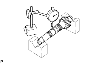
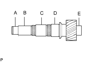
| 1. INSPECT NO. 1 OUTPUT SHAFT |
Check the No. 1 output shaft for wear and damage.
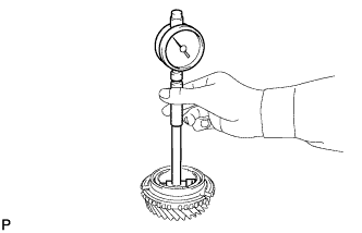
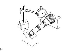
Using a dial indicator, check the No. 1 output shaft runout.
- Maximum runout:
- 0.03 mm (0.0012 in.)
If the runout exceeds the maximum, replace the No. 1 output shaft.
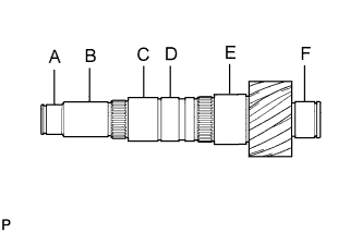
Using a micrometer, measure the outer diameter of the No. 1 output shaft journal surface.
- Standard:
Measured Part
| Outer Diameter mm (in.)
|
A
| 32.002 to 32.018 (1.2599 to 1.2605)
|
B
| 35.984 to 36.000 (1.4167 to 1.4173)
|
C
| 42.000 to 41.984 (1.6535 to 1.6529)
|
D
| 42.000 to 41.989 (1.6535 to 1.6531)
|
E
| 47.000 to 46.984 (1.8504 to 1.8498)
|
F
| 36.002 to 36.018 (1.4174 to 1.4180)
|
If the outer diameter is below the minimum, replace the No. 1 output shaft.
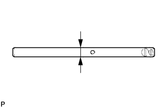
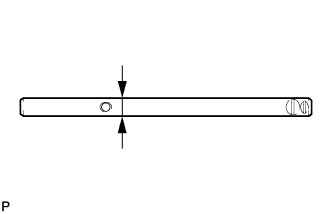
| 2. INSPECT 1ST AND 2ND SHIFT FORK SHAFT |
Using a micrometer, measure the outer diameter of the 1st and 2nd shift fork shaft.
- Standard outer diameter:
- 13.982 to 14.00 mm (0.5505 to 0.5512 in.)
- Minimum outer diameter:
- 13.982 mm (0.5505 in.)
If the outer diameter is less than the minimum, replace the 1st and 2nd shift fork shaft.
| 3. INSPECT 3RD AND 4TH SHIFT FORK SHAFT |
Using a micrometer, measure the outer diameter of the 3rd and 4th shift fork shaft.
- Standard outer diameter:
- 13.982 to 14.00 mm (0.5505 to 0.5512 in.)
- Minimum outer diameter:
- 13.982 mm (0.5505 in.)
If the outer diameter is less than the minimum, replace the 3rd and 4th shift fork shaft.
| 4. INSPECT 5TH AND 6TH SHIFT FORK SHAFT |
Using a micrometer, measure the outer diameter of the 5th and 6th shift fork shaft.
- Standard outer diameter:
- 13.982 to 14.00 mm (0.5505 to 0.5512 in.)
- Minimum outer diameter:
- 13.982 mm (0.5505 in.)
If the outer diameter is less than the minimum, replace the 5th and 6th shift fork shaft.
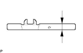
| 5. INSPECT REVERSE SHIFT FORK SHAFT |
Using a micrometer, measure the outer diameter of the reverse shift fork shaft.
- Standard outer diameter:
- 13.982 to 14.00 mm (0.5505 to 0.5512 in.)
- Minimum outer diameter:
- 13.982 mm (0.5505 in.)
If the outer diameter is less than the minimum, replace the reverse shift fork shaft.
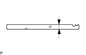
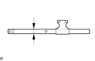
| 6. INSPECT NO. 5 GEAR SHIFT FORK SHAFT |
Using a micrometer, measure the outer diameter of the No. 5 gear shift fork shaft.
- Standard outer diameter:
- 15.966 to 15.984 mm (0.6286 to 0.6293 in.)
- Minimum outer diameter:
- 15.966 mm (0.6286 in.)
If the outer diameter is less than the minimum, replace the No. 5 gear shift fork shaft.
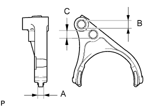
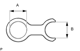
| 7. INSPECT NO. 1 GEAR SHIFT FORK |
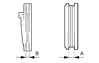
Using vernier calipers, measure the No. 1 gear shift fork.
- Standard inside diameter and thickness:
- A:
- 9.50 to 9.80 mm (0.3740 to 0.3858 in.)
- B:
- 14.010 to 14.043 mm (0.5516 to 0.5529 in.)
If the inside diameter or thickness is not as specified, replace the No. 1 gear shift fork.
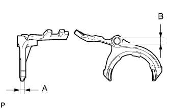
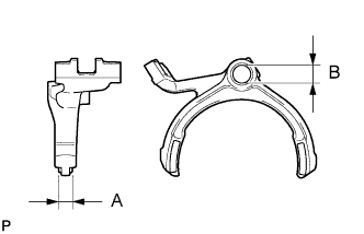
| 8. INSPECT NO. 2 GEAR SHIFT FORK |
Using vernier calipers, measure the No. 2 gear shift fork.
- Standard inside diameter and thickness:
- A:
- 9.50 to 9.80 mm (0.3740 to 0.3858 in.)
- B:
- 14.010 to 14.043 mm (0.5516 to 0.5529 in.)
- C:
- 14.70 to 15.30 mm (0.5787 to 0.6024 in.)
If the inside diameter or thickness is not as specified, replace the No. 2 gear shift fork.
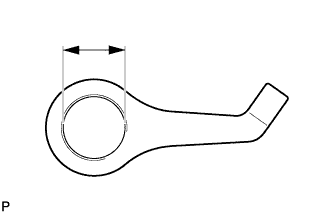
| 9. INSPECT NO. 3 GEAR SHIFT FORK |
Using vernier calipers, measure the No. 3 gear shift fork.
- Standard inside diameter and thickness:
- A:
- 9.50 to 9.80 mm (0.3740 to 0.3858 in.)
- B:
- 14.010 to 14.043 mm (0.5516 to 0.5529 in.)
If the inside diameter or thickness is not as specified, replace the No. 3 gear shift fork.
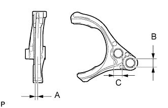
| 10. INSPECT REVERSE SHIFT FORK |
Using vernier calipers, measure the reverse shift fork.
- Standard inside diameter and thickness:
- A:
- 4.40 to 4.56 mm (0.1732 to 0.1795 in.)
- B:
- 14.010 to 14.043 mm (0.5516 to 0.5529 in.)
- C:
- 14.7 to 15.3 mm (0.5787 to 0.6024 in.)
If the inside diameter or thickness is not as specified, replace the reverse shift fork.
| 11. INSPECT NO. 2 GEAR SHIFT HEAD |
Using vernier calipers, measure the No. 2 gear shift head.
- Standard inside diameter:
- 13.994 to 14.054 mm (0.5509 to 0.5533 in.)
- Maximum inside diameter:
- 14.054 mm (0.5533 in.)
If the inside diameter exceeds the maximum, replace the No. 2 gear shift head.
| 12. INSPECT NO. 3 GEAR SHIFT HEAD |
Using vernier calipers, measure the No. 3 gear shift head.
- Standard inside diameter:
- A:
- 15.994 to 16.054 mm (0.6297 to 0.6320 in.)
- B:
- 14.20 to 14.25 mm (0.5591 to 0.5610 in.)
- Maximum inside diameter:
- A:
- 16.054 mm (0.6320 in.)
- B:
- 14.25 mm (0.5610 in.)
If the inside diameter exceeds the maximum, replace the No. 3 gear shift head.
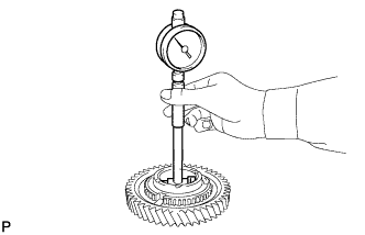
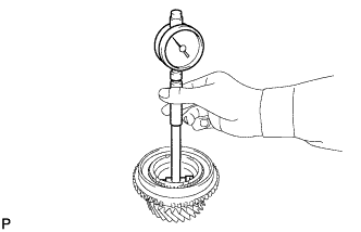
| 13. INSPECT 1ST DRIVEN GEAR |
Using a cylinder gauge, measure the inside diameter of the 1st driven gear.
- Standard inside diameter:
- 53.015 to 53.040 mm (2.0872 to 2.0882 in.)
- Maximum inside diameter:
- 53.040 mm (2.0882 in.)
If the inside diameter exceeds the maximum, replace the 1st driven gear.
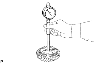
| 14. INSPECT 2ND DRIVEN GEAR |
Using a cylinder gauge, measure the inside diameter of the 2nd driven gear.
- Standard inside diameter:
- 56.015 to 56.030 mm (2.2053 to 2.2059 in.)
- Maximum inside diameter:
- 56.030 mm (2.2059 in.)
If the inside diameter exceeds the maximum, replace the 2nd driven gear.
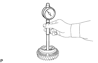
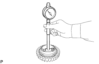
| 15. INSPECT 3RD DRIVEN GEAR |
Using a cylinder gauge, measure the inside diameter of the 3rd driven gear.
- Standard inside diameter:
- 42.015 to 42.040 mm (1.6541 to 1.6551 in.)
- Maximum inside diameter:
- 42.040 mm (1.6551 in.)
If the inside diameter exceeds the maximum, replace the 3rd driven gear.
| 16. INSPECT 4TH DRIVEN GEAR |
Using a cylinder gauge, measure the inside diameter of the 4th driven gear.
- Standard inside diameter:
- 48.015 to 48.040 mm (1.8904 to 1.8913 in.)
- Maximum inside diameter:
- 48.040 mm (1.8913 in.)
If the inside diameter exceeds the maximum, replace the 4th driven gear.
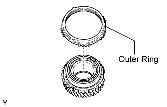
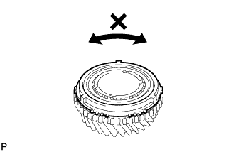
| 17. INSPECT 1ST DRIVEN GEAR SYNCHRONIZER RING SET |
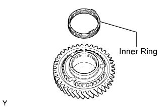
Coat the 1st driven gear synchronizer ring set with gear oil.
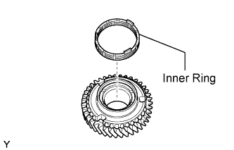
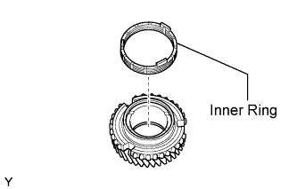
Install the inner ring onto the 1st driven gear.
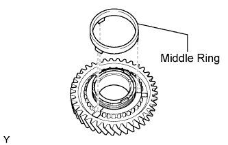
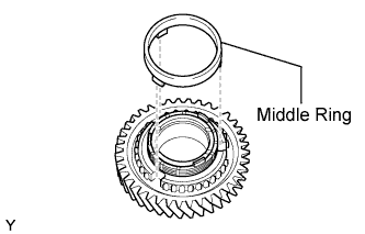
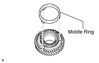
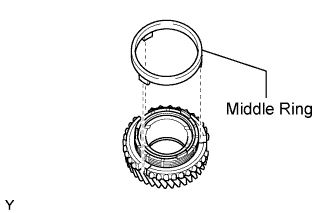
Install the middle ring onto the 1st driven gear.
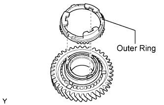
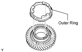
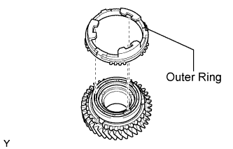
Install the outer ring onto the 1st driven gear.
Coat the 1st driven gear with gear oil.
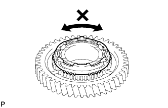
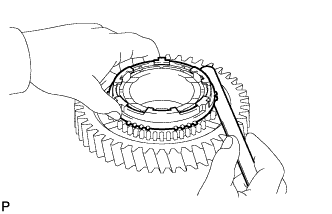
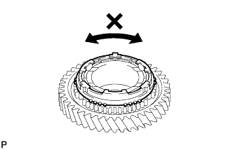
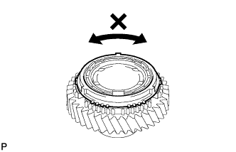
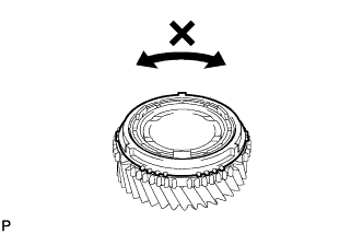
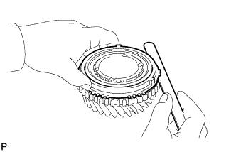
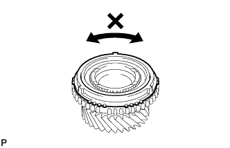
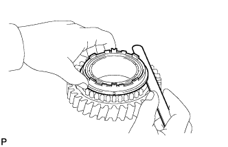
Check that the outer and inner synchronizer rings do not turn when the outer ring is pushed to the 1st driven gear.
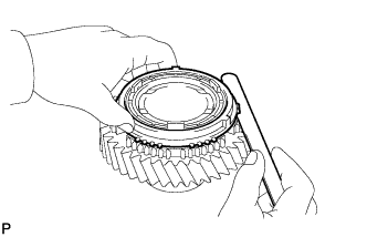
Using a feeler gauge, measure the clearance between the synchronizer ring and the 1st gear spline end.
- Standard clearance:
- 0.98 to 1.82 mm (0.039 to 0.072 in.)
- Minimum clearance:
- 0.98 mm (0.039 in.)
If the clearance is below the minimum, replace the 1st driven gear synchronizer ring set.
| 18. INSPECT 2ND DRIVEN GEAR SYNCHRONIZER RING SET |
Coat the 2nd driven gear synchronizer ring set with gear oil.
Install the inner ring onto the 2nd driven gear.
Install the middle ring onto the 2nd driven gear.
Install the outer ring onto the 2nd driven gear.
Coat the 2nd driven gear with gear oil.
Check that the outer and inner synchronizer rings do not turn when the outer ring is pushed to the 2nd driven gear.
Using a feeler gauge, measure the clearance between the synchronizer ring and the 2nd gear spline end.
- Standard clearance:
- 1.08 to 1.92 mm (0.043 to 0.076 in.)
- Minimum clearance:
- 1.08 mm (0.043 in.)
If the clearance is below the minimum, replace the 2nd driven gear synchronizer ring set.
| 19. INSPECT 3RD DRIVEN GEAR SYNCHRONIZER RING SET |
Coat the 3rd driven gear synchronizer ring set with gear oil.
Install the inner ring onto the 3rd driven gear.
Install the middle ring onto the 3rd driven gear.
Install the outer ring onto the 3rd driven gear.
Coat the 3rd driven gear with gear oil.
Check that the outer and inner synchronizer rings do not turn when the outer ring is pushed to the 3rd driven gear.
Using a feeler gauge, measure the clearance between the 3rd gear synchronizer ring and the spline end.
- Standard clearance:
- 1.00 to 2.00 mm (0.039 to 0.079 in.)
- Minimum clearance:
- 1.00 mm (0.039 in.)
If the clearance is below the minimum, replace the 3rd driven gear synchronizer ring.
| 20. INSPECT 4TH DRIVEN GEAR SYNCHRONIZER RING SET |
Coat the 4th driven gear synchronizer ring set with gear oil.
Install the inner ring onto the 4th driven gear.
Install the middle ring onto the 4th driven gear.
Install the outer ring onto the 4th driven gear.
Coat the 4th driven gear with gear oil.
Check that the outer and inner synchronizer rings do not turn when the outer ring is pushed to the 4th driven gear.
Using a feeler gauge, measure the clearance between the 4th gear synchronizer ring and the spline end.
- Standard clearance:
- 0.92 to 1.88 mm (0.036 to 0.074 in.)
- Minimum clearance:
- 0.92 mm (0.036 in.)
If the clearance is below the minimum, replace the 4th driven gear synchronizer ring.
| 21. INSPECT NO. 1 TRANSMISSION HUB SLEEVE |
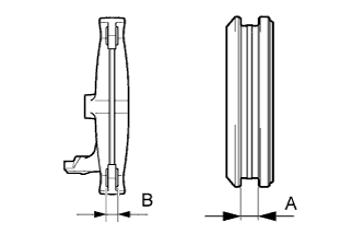
Using vernier calipers, measure the clearance between the No. 1 transmission hub sleeve and the No. 1 gear shift fork.
- Standard clearance (A - B):
- 0.10 to 0.50 mm (0.0039 to 0.0197 in.)
If the clearance is outside the specifications, replace the No. 1 transmission hub sleeve and No. 1 gear shift fork.
| 22. INSPECT NO. 2 TRANSMISSION HUB SLEEVE |
Using vernier calipers, measure the clearance between the No. 2 transmission hub sleeve and the No. 2 gear shift fork.
- Standard clearance (A - B):
- 0.10 to 0.50 mm (0.0039 to 0.0197 in.)
If the clearance is outside the specifications, replace the No. 2 transmission hub sleeve and No. 2 gear shift fork.
| 23. INSPECT NO. 2 OUTPUT SHAFT |
Check the No. 2 output shaft for wear and damage.
Using a dial indicator, check the No. 2 output shaft runout.
- Maximum runout:
- 0.03 mm (0.0012 in.)
If the runout exceeds the maximum, replace the No. 2 output shaft.
Using a micrometer, measure the outer diameter of the No. 2 output shaft journal surface.
- Standard:
Measured Part
| Outer Diameter mm (in.)
|
A
| 32.002 to 32.018 (1.2599 to 1.2605)
|
B
| 35.984 to 36.000 (1.4167 to 1.4173)
|
C
| 41.984 to 42.000 (1.6529 to 1.6535)
|
D
| 46.984 to 47.000 (1.8498 to 1.8504)
|
E
| 35.002 to 35.018 (1.3780 to 1.3787)
|
If the outer diameter is below the minimum, replace the No. 2 output shaft.
| 24. INSPECT 5TH DRIVEN GEAR |
Using a cylinder gauge, measure the inside diameter of the 5th driven gear.
- Standard inside diameter:
- 48.015 to 48.040 mm (1.8904 to 1.8913 in.)
- Maximum inside diameter:
- 48.040 mm (1.8913 in.)
If the inside diameter exceeds the maximum, replace the 5th driven gear.
| 25. INSPECT 6TH DRIVEN GEAR |
Using a cylinder gauge, measure the inside diameter of the 6th driven gear.
- Standard inside diameter:
- 42.015 to 42.040 mm (1.6541 to 1.6551 in.)
- Maximum inside diameter:
- 42.040 mm (1.6551 in.)
If the inside diameter exceeds the maximum, replace the 6th driven gear.
| 26. INSPECT REVERSE DRIVEN GEAR |
Using a cylinder gauge, measure the inside diameter of the reverse driven gear.
- Standard inside diameter:
- 53.015 to 53.040 mm (2.0872 to 2.0882 in.)
- Maximum inside diameter:
- 53.040 mm (2.0882 in.)
If the inside diameter exceeds the maximum, replace the reverse driven gear.
| 27. INSPECT 5TH DRIVEN GEAR SYNCHRONIZER RING |
Coat the 5th driven gear synchronizer ring with gear oil.
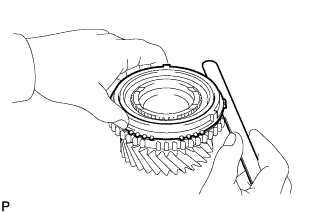
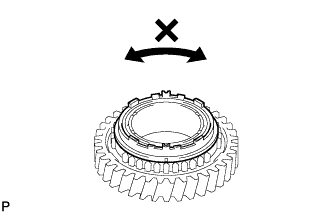
Check that the synchronizer ring does not turn when the ring is pushed to the 5th driven gear.
Using a feeler gauge, measure the clearance between the synchronizer ring and the 5th driven gear spline end.
- Standard clearance:
- 0.80 to 1.60 mm (0.031 to 0.063 in.)
- Minimum clearance:
- 0.80 mm (0.031 in.)
If the clearance is below the minimum, replace the 5th driven gear synchronizer ring.
| 28. INSPECT 6TH DRIVEN GEAR SYNCHRONIZER RING |
Coat the 6th driven gear synchronizer ring with gear oil.
Check that the synchronizer ring does not turn when the ring is pushed to the 6th driven gear.
Using a feeler gauge, measure the clearance between the synchronizer ring and the 6th driven gear spline end.
- Standard clearance:
- 0.80 to 1.60 mm (0.031 to 0.063 in.)
- Minimum clearance:
- 0.80 mm (0.031 in.)
If the clearance is below the minimum, replace the 6th driven gear synchronizer ring.
| 29. INSPECT REVERSE DRIVEN GEAR SYNCHRONIZER RING |
Coat the reverse driven gear synchronizer ring with gear oil.
Check that the synchronizer ring does not turn when the ring is pushed to the reverse driven gear.
Using a feeler gauge, measure the clearance between the synchronizer ring and the reverse driven gear spline end.
- Standard clearance:
- 0.68 to 1.32 mm (0.027 to 0.052 in.)
- Minimum clearance:
- 0.68 mm (0.027 in.)
If the clearance is below the minimum, replace the reverse driven gear synchronizer ring.
| 30. INSPECT NO. 3 TRANSMISSION HUB SLEEVE |
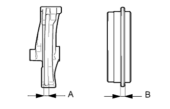
Using vernier calipers, measure the clearance between the No. 3 transmission hub sleeve and the No. 3 gear shift fork.
- Standard clearance (A - B):
- 0.10 to 0.50 mm (0.0039 to 0.0197 in.)
If the clearance is outside the specifications, replace the No. 3 transmission hub sleeve and No. 3 gear shift fork.
| 31. INSPECT NO. 4 TRANSMISSION HUB SLEEVE |
Using vernier calipers, measure the clearance between the No. 4 transmission hub sleeve and the reverse shift fork.
- Standard clearance (A - B):
- 0.15 to 0.41 mm (0.0059 to 0.0161 in.)
If the clearance is outside the specifications, replace the No. 4 transmission hub sleeve and reverse shift fork.