Трансмиссия. COROLLA, AURIS. ZZE150 ZRE151,152 NDE150
Механическая Трансмиссия 'Multimode' C53A. COROLLA, AURIS. ZZE150 ZRE151,152 NDE150
CHECK HARNESS AND CONNECTOR (TCM - COMBINATION METER ASSEMBLY)
СИСТЕМА МЕХАНИЧЕСКОЙ ТРАНСМИССИИ 'MULTIMODE' - Цепь контрольной лампы механической трансмиссии 'MULTIMODE' |
DESCRIPTION
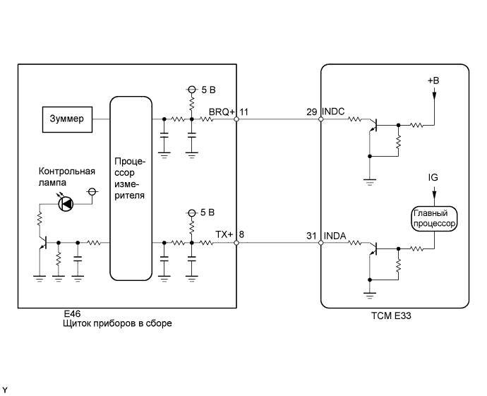
The combination meter interprets the multi-mode manual transaxle system condition according to the information from the INDC and INDA circuits, and if necessary, illuminates (blinks) the multi-mode manual transmission warning light and sounds the buzzer.- INDC Terminal Circuit:
The battery voltage is constantly supplied to the INDC circuit. If the INDC circuit is open, the combination meter detects a malfunction in the circuit and illuminates the multi-mode manual transmission warning light. The INDC circuit is used to send the multi-mode manual transmission warning light signal to the combination meter when the ignition switch is off. - INDA Terminal Circuit:
Power is supplied to the INDA circuit when the ignition switch is on (IG). While the ignition switch is on (IG), the combination meter controls the multi-mode manual transmission warning light ON/OFF condition according to the signal from the INDA circuit. The INDA circuit is used to send the signal for multi-mode manual transmission warning light and shift position indicator to the combination meter.
| INDA circuit state (at combination meter) | Normal | Inconsistent signal input (3 seconds or more) | Interrupted signal input (3 seconds or more) | |||
| INDC circuit (at combination meter) | Normal | +B short or open | Normal | +B short or open | Normal | +B short or open |
| Shift position indicator *1 | ON depends on communication signal | ON depends on communication signal | OFF | OFF | OFF | OFF |
| Multi-mode manual transmission warning light | ON depends on communication signal | ON depends on communication signal | ON | ON | ON | ON |
| Buzzer (Built in combination meter) *2 | ON | ON | ON | ON | ON | ON |
*2: The buzzer sounds when the following conditions are met in addition to those above.
- The shift lever is in any position except N.
- The driver's door is open.
- Vehicle speed is 9 km/h or less.
- Engine speed is 400 rpm or more.
| INDA circuit state (at combination meter) | Normal | Inconsistent signal input (3 seconds or more) | Interrupted signal input (3 seconds or more) | |||
| INDC circuit state (at combination meter) | Normal | +B short or open | Normal | +B short or open | Normal | +B short or open |
| Shift position indicator *1 | ON depends on communication signal | ON depends on communication signal | OFF | OFF | OFF | OFF |
| Multi-mode manual transmission warning light | ON depends on communication signal | ON depends on communication signal | ON | ON | ON (turns OFF 8 seconds after IG OFF) | ON |
| Buzzer (Built in combination meter) | OFF | OFF | OFF | ON | OFF | ON |
WIRING DIAGRAM
INSPECTION PROCEDURE
- УКАЗАНИЕ:
- Check that the multi-mode manual transmission warning light and shift position indicator light come on.
Under normal conditions, the shift position indicator indicates the current gear position while the ignition switch is turned on (IG), and the multi-mode manual transmission warning light comes on for bulb check for approximately 5 seconds when the ignition switch is turned from off to on (IG).
If the shift position indicator light does not come on, the INDA circuit may be malfunctioning. If the multi-mode manual transmission warning light does not come on, the INDA and/or INDC circuits may be malfunctioning. - The buzzer built into the combination meter sounds when the following conditions are met.
- The shift lever is in any position except N.
- The driver's door is open.
- Vehicle speed is 10 km/h (6.21 mph) or less.
- Engine speed is 400 rpm or more.
| 1.CHECK HARNESS AND CONNECTOR (TCM - COMBINATION METER ASSEMBLY) |
Disconnect the TCM connector.
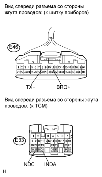 |
Disconnect the combination meter connector.
Measure the resistance according to the value(s) in the table below.
- Standard resistance:
Tester Connection Condition Specified Condition E33-29 (INDC) - E46-11 (BRQ+) Always Below 1 Ω E33-31 (INDA) - E46-8 (TX+) ↑ Below 1 Ω E33-29 (INDC) - Body ground ↑ 10 kΩ or higher E33-31 (INDA) - Body ground ↑ 10 kΩ or higher
Reconnect the TCM connector.
Reconnect the combination meter connector.
|
| ||||
| OK | |
| 2.INSPECT COMBINATION METER |
Disconnect the E33 TCM connector.
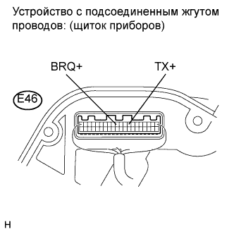 |
Measure the voltage between the terminal of the combination meter and the body ground.
- Standard voltage:
Tester Connection Condition Specified Condition E46-8 (TX+) - Body ground Always 3.64 V or higher E46-11 (BRQ+) - Body ground ↑ 3.64 V or higher
Reconnect the E33 TCM connector.
|
| ||||
| OK | ||
| ||