DESCRIPTION
WIRING DIAGRAM
INSPECTION PROCEDURE
READ VALUE USING INTELLIGENT TESTER
INSPECT TCM (IG TERMINAL VOLTAGE)
CHECK HARNESS AND CONNECTOR (TCM - BODY GROUND)
INSPECT FUSE (IGN FUSE)
INSPECT FUSE (IG2 FUSE)
INSPECT ENGINE ROOM JUNCTION BLOCK (IG2 RELAY)
CHECK HARNESS AND CONNECTOR (IGN FUSE - TCM)
CHECK HARNESS AND CONNECTOR (IG2 RELAY - IGN FUSE)
CHECK HARNESS AND CONNECTOR (IG2 RELAY - BODY GROUND)
INSPECT FUSE (IG2 NO. 2 FUSE)
CHECK HARNESS AND CONNECTOR (IG2 RELAY - IG2 NO. 2 FUSE)
CHECK HARNESS AND CONNECTOR (IG2 NO. 2 FUSE - IGNITION SWITCH)
INSPECT IGNITION SWITCH
INSPECT FUSE (AM2 FUSE)
CHECK HARNESS AND CONNECTOR (IGNITION SWITCH - AM2 FUSE)
СИСТЕМА МЕХАНИЧЕСКОЙ ТРАНСМИССИИ 'MULTIMODE' - Сигнальная цепь зажигания |
DESCRIPTION
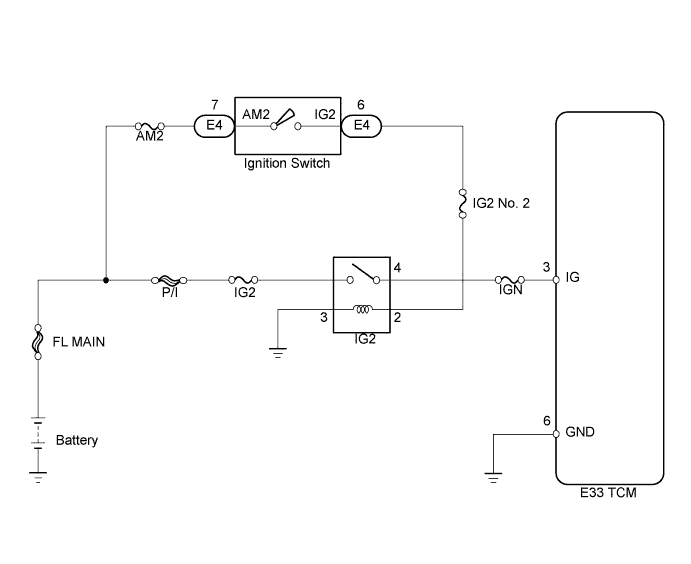
When the ignition switch is turned on (IG), the battery voltage is applied to terminal IG of the TCM. Power is supplied to the TCM via terminals +B and IG. The TCM interprets the ignition switch condition through the potential at the IG terminal.
WIRING DIAGRAM
INSPECTION PROCEDURE
| 1.READ VALUE USING INTELLIGENT TESTER |
Connect the intelligent tester to the DLC3
Turn the ignition switch on (IG) and turn the tester ON.
Select the following menu items: Powertrain / Multi-Mode M/T / Data List.
Read the value.
Items
[Abbreviation]
| Measurement Items: Display
| Normal Conditions
| Diagnostic Notes
|
Ignition Signal
[Ignition Sig]
| Ignition switch signal:
Open (OFF) or +B (ON)
| +B: Ignition switch on (IG)
| -
|
- OK:
- [+B] is displayed in the item [Ignition Signal] when the ignition switch is turned on (IG).
- Result:
| | PROCEED TO NEXT CIRCUIT INSPECTION SHOWN IN PROBLEM SYMPTOMS TABLE |
|
|
| 2.INSPECT TCM (IG TERMINAL VOLTAGE) |
Disconnect the TCM connector.
Turn the ignition switch on (IG).
Measure the voltage between the terminal of the TCM connector and the body ground.
- Standard voltage:
Tester Connection
| Switch Condition
| Specified Condition
|
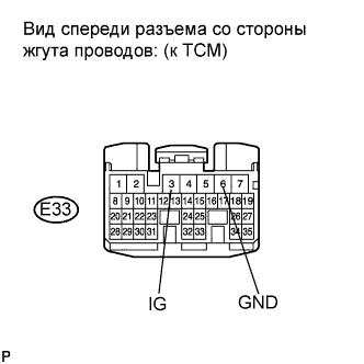
E33-3 (IG) - E33-6 (GND)
| Ignition switch off
| Below 1 V
|
E33-3 (IG) - E33-6 (GND)
| Ignition switch on (IG)
| 11 to 14 V
|
- Result:
Reconnect the TCM connector.
| 3.CHECK HARNESS AND CONNECTOR (TCM - BODY GROUND) |
Disconnect the TCM connector.
Measure the resistance according to the value(s) in the table below.
- Standard resistance:
Tester Connection
| Condition
| Specified Condition
|
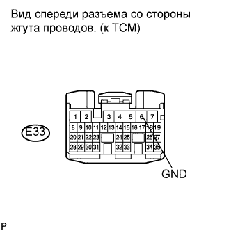
E33-6 (GND) - Body ground
| Always
| Below 1 Ω
|
Reconnect the TCM connector.
| | REPAIR OR REPLACE HARNESS OR CONNECTOR (TCM - BODY GROUND) |
|
|
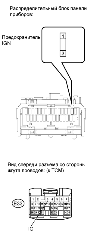
| 4.INSPECT FUSE (IGN FUSE) |
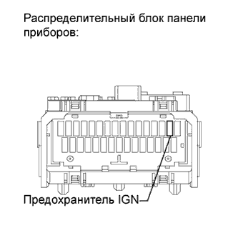
Remove the IGN fuse from the instrument panel junction block.
Measure the resistance according to the value(s) in the table below.
- Standard resistance:
Tester Connection
| Condition
| Specified Condition
|
IGN fuse
| Always
| Below 1 Ω
|
Reinstall the IGN fuse.
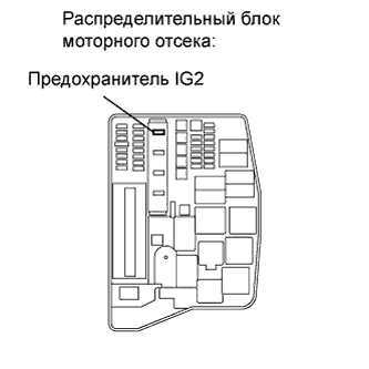
| 5.INSPECT FUSE (IG2 FUSE) |
Remove the IG2 fuse from the engine room junction block.
Measure the resistance according to the value(s) in the table below.
- Standard resistance:
Tester Connection
| Condition
| Specified Condition
|
IG2 fuse
| Always
| Below 1 Ω
|
Reinstall the IG2 fuse.
| | REPLACE FUSE (IG2 RELAY - IGN FUSE) |
|
|
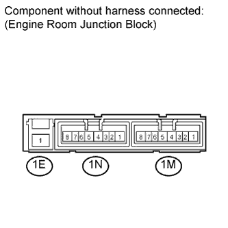
| 6.INSPECT ENGINE ROOM JUNCTION BLOCK (IG2 RELAY) |
Remove the engine room junction block from the engine room relay block.
Disconnect the engine room junction block connector.
Measure the IG2 relay resistance.
- Standard resistance:
Tester Connection
| Condition
| Specified Condition
|
1E-1 - 1M-4
| Voltage is not applied between terminals 1M-2 and 1M-3
| 10 kΩ or higher
|
Apply battery voltage terminals 1M-2 and 1M-3
| Below 1 Ω
|
Reconnect the engine room junction block connector.
Reinstall the engine room junction block.
| | REPLACE ENGINE ROOM JUNCTION BLOCK |
|
|
| 7.CHECK HARNESS AND CONNECTOR (IGN FUSE - TCM) |
Disconnect the TCM connectors.
Remove the IGN fuse from the instrument panel junction block.
Measure the resistance according to the value(s) in the table below.
- Standard resistance (Check for open):
Tester Connection
| Condition
| Specified Condition
|
2 (IGN fuse) - E33-3 (IG)
| Always
| Below 1 Ω
|
- Standard resistance (Check for short):
Tester Connection
| Condition
| Specified Condition
|
2 (IGN fuse) or E33-3 (IG) - Body ground
| Always
| 10 kΩ or higher
|
Reconnect the TCM connector.
Reinstall the IGN fuse.
| | REPAIR OR REPLACE HARNESS OR CONNECTOR (IGN FUSE - TCM) |
|
|
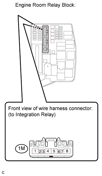
| 8.CHECK HARNESS AND CONNECTOR (IG2 RELAY - IGN FUSE) |
Remove the engine room junction block from the engine room relay block.
Disconnect the engine room junction block connector.
Remove the IGN fuse from the instrument panel junction block.
Measure the resistance according to the value(s) in the table below.
- Standard resistance (Check for open):
Tester Connection
| Condition
| Specified Condition
|
1M-4 - 1 (IGN fuse)
| Always
| Below 1 Ω
|
- Standard resistance (Check for short):
Tester Connection
| Condition
| Specified Condition
|
1M-4 or 1 (IGN fuse) - Body ground
| Always
| 10 kΩ or higher
|
Reconnect the engine room junction block connector.
Reinstall the engine room junction block.
Reinstall the IGN fuse.
| | REPAIR OR REPLACE HARNESS OR CONNECTOR (IG2 RELAY - IGN FUSE) |
|
|
| 9.CHECK HARNESS AND CONNECTOR (IG2 RELAY - BODY GROUND) |
Remove the engine room junction block from the engine room relay block.
Disconnect the engine room junction block connector.
Measure the resistance according to the value(s) in the table below.
- Standard resistance:
Tester Connection
| Condition
| Specified Condition
|
1M-3 - Body ground
| Always
| Below 1 Ω
|
Reconnect the engine room junction block connector.
Reinstall the engine room junction block.
| | REPAIR OR REPLACE HARNESS OR CONNECTOR (IG2 RELAY - BODY GROUND) |
|
|
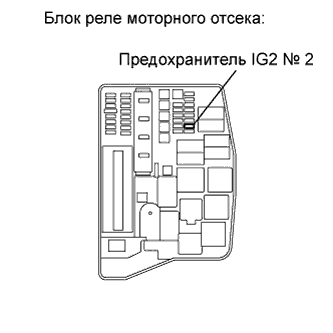
| 10.INSPECT FUSE (IG2 NO. 2 FUSE) |
Remove the IG2 No. 2 fuse from the engine room junction block.
Measure the resistance according to the value(s) in the table below.
- Standard resistance:
Tester Connection
| Condition
| Specified Condition
|
IG2 No. 2 fuse
| Always
| Below 1 Ω
|
Reinstall the IG2 No. 2 fuse.
| | REPLACE FUSE (IG2 NO. 2 FUSE) |
|
|
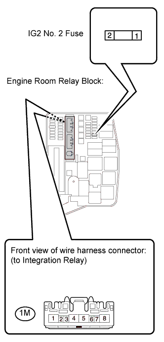
| 11.CHECK HARNESS AND CONNECTOR (IG2 RELAY - IG2 NO. 2 FUSE) |
Remove the engine room junction block from the engine room relay block.
Disconnect the engine room junction block connector.
Remove the IG2 No. 2 fuse from the engine room relay block.
Measure the resistance according to the value(s) in the table below.
- Standard resistance (Check for open):
Tester Connection
| Condition
| Specified Condition
|
1M-2 - 2 (IG2 No. 2 fuse)
| Always
| Below 1 Ω
|
- Standard resistance (Check for short):
Tester Connection
| Condition
| Specified Condition
|
1M-2 or 2 (IG2 No. 2 fuse) - Body ground
| Always
| 10 kΩ or higher
|
Reconnect the engine room junction block connector.
Reinstall the engine room junction block.
Reinstall the IG2 No. 2 fuse.
| | REPAIR OR REPLACE HARNESS OR CONNECTOR (IG2 RELAY - IG2 NO. 2 FUSE) |
|
|
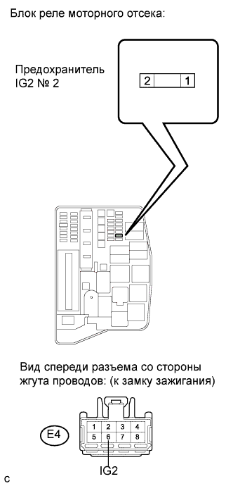
| 12.CHECK HARNESS AND CONNECTOR (IG2 NO. 2 FUSE - IGNITION SWITCH) |
Disconnect the ignition switch connector.
Remove the IG2 No. 2 fuse from the engine room relay block.
Measure the resistance according to the value(s) in the table below.
- Standard resistance (Check for open):
Tester Connection
| Condition
| Specified Condition
|
1 (IG2 No. 2 fuse) - E4-6 (IG2)
| Always
| Below 1 Ω
|
- Standard resistance (Check for short):
Tester Connection
| Condition
| Specified Condition
|
1 (IG2 No. 2 fuse) or E4-6 (IG2) - Body ground
| Always
| 10 kΩ or higher
|
Reconnect the ignition switch connector.
Reinstall the IG2 No. 2 fuse.
- Result:
| A |
|
|
|
| REPAIR OR REPLACE HARNESS OR CONNECTOR (IG2 NO. 2 FUSE - IGNITION SWITCH) |
|
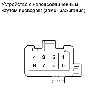
| 13.INSPECT IGNITION SWITCH |
Disconnect the ignition switch connector.
Measure the resistance according to the value(s) in the table below.
- Standard resistance:
Tester Connection
| Ignition Switch Position
| Specified Condition
|
All Terminals
| LOCK
| 10 kΩ or higher
|
2 - 4
| ACC
| Below 1 Ω
|
1 - 2 - 4, 5 - 6
| ON
|
1 - 3 - 4, 5 - 6 - 7
| START
|
Reconnect the ignition switch connector.
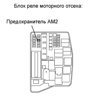
| 14.INSPECT FUSE (AM2 FUSE) |
Remove the AM2 fuse from the engine room relay block.
Measure the resistance according to the value(s) in the table below.
- Standard resistance:
Tester Connection
| Condition
| Specified Condition
|
AM2 fuse
| Always
| Below 1 Ω
|
Reinstall the AM2 fuse.
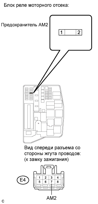
| 15.CHECK HARNESS AND CONNECTOR (IGNITION SWITCH - AM2 FUSE) |
Disconnect the ignition switch connector.
Remove the AM2 fuse from the engine room relay block.
Measure the resistance according to the value(s) in the table below.
- Standard resistance (Check for open):
Tester Connection
| Condition
| Specified Condition
|
E4-7 (AM2) - 2 (AM2 fuse)
| Always
| Below 1 Ω
|
- Standard resistance (Check for short):
Tester Connection
| Condition
| Specified Condition
|
E4-7 (AM2) or 2 (AM2 fuse) - Body ground
| Always
| 10 kΩ or higher
|
Reconnect the ignition switch connector.
Reinstall the AM2 fuse.
| | REPAIR OR REPLACE HARNESS OR CONNECTOR (IGNITION SWITCH - AM2 FUSE) |
|
|
| OK |
|
|
|
| REPAIR OR REPLACE HARNESS OR CONNECTOR (AM2 FUSE - BATTERY) |
|