DESCRIPTION
WIRING DIAGRAM
INSPECTION PROCEDURE
READ VALUE USING INTELLIGENT TESTER
CHECK HARNESS AND CONNECTOR (ST RELAY - BODY GROUND)
INSPECT ST RELAY
CHECK ST RELAY (POWER SOURCE)
CHECK HARNESS AND CONNECTOR (ST RELAY - TCM)
CHECK HARNESS AND CONNECTOR (IGNITION SWITCH - BATTERY)
INSPECT IGNITION SWITCH ASSEMBLY
CHECK HARNESS AND CONNECTOR (IGNITION SWITCH - PARK/NEUTRAL POSITION SWITCH)
INSPECT PARK/NEUTRAL POSITION SWITCH
CHECK HARNESS AND CONNECTOR (TCM - PARK/NEUTRAL POSITION SWITCH)
СИСТЕМА МЕХАНИЧЕСКОЙ ТРАНСМИССИИ 'MULTIMODE' - Сигнальная цепь стартера |
DESCRIPTION
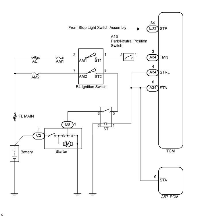
w/o Entry and Start System:In this vehicle, the ST relay that supplies power to the starter motor is operated by the STRL signal from of the TCM. When the appropriate vehicle conditions are satisfied, the brake pedal is depressed (STP) and the transaxle gear is in neutral (TMN), the engine can be cranked. If the brake pedal is not depressed or the transaxle gear is not in neutral, the engine cannot be cranked. During cranking, the ST relay operation signal (STA signal) is input into the STA terminal of the TCM, and is used to control the multi-mode manual transaxle system.
WIRING DIAGRAM
INSPECTION PROCEDURE
- УКАЗАНИЕ:
- If DTC P0703 is output, troubleshoot this code first.
| 1.READ VALUE USING INTELLIGENT TESTER |
Connect an intelligent tester to the DLC3.
Turn the ignition switch on (IG) and turn the tester ON.
Select the following menu items: Powertrain / Multi-Mode M/T / Data List / STA Switch Signal.
Check the value displayed on the tester when the ignition switch is turned on (IG) and the engine starts.
Items
[Abbreviation]
| Measurement Items: Display
| Normal Conditions
| Diagnostic Notes
|
STA Switch Signal
[STA SW Sig]
| STA signal:
ON or OFF
| ON: During cranking
| -
|
- OK:
- [ON] displays in the STA Switch Signal during cranking.
- Result:
| | PROCEED TO NEXT CIRCUIT INSPECTION SHOWN IN PROBLEM SYMPTOMS TABLE |
|
|
| 2.CHECK HARNESS AND CONNECTOR (ST RELAY - BODY GROUND) |
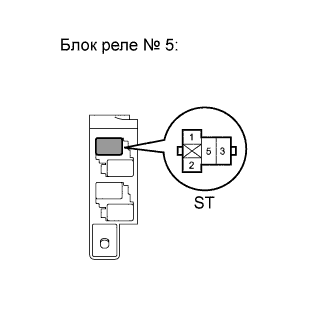
Remove the ST relay from the No. 5 relay block.
Measure the resistance according to the value(s) in the table below.
- Standard resistance:
Tester Connection
| Condition
| Specified Condition
|
ST relay terminal 2 - Body ground
| Always
| Below 1 Ω
|
Reconnect the ST relay.
| | REPAIR OR REPLACE HARNESS OR CONNECTOR |
|
|
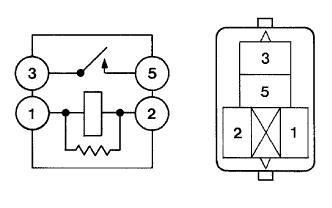
Remove the ST relay from the No. 5 relay block.
Measure the resistance according to the value(s) in the table below.
- Standard resistance:
Tester Connection
| Condition
| Specified Condition
|
3 - 5
| Voltage is not applied between terminals 1 and 2
| 10 kΩ or higher
|
3 - 5
| Apply the battery voltage between terminals 1 and 2
| Below 1 Ω
|
Reinstall the ST relay.
| 4.CHECK ST RELAY (POWER SOURCE) |
Remove the ST relay from the No. 5 relay block.
Measure the voltage according to the value(s) in the table below.
- Standard voltage:
Tester Connection
| Condition
| Specified Condition
|
ST relay terminal 1 - Body ground
| Brake pedal depressed, shift lever position N and ignition switch to the START position
| 11 to 14 V
|
Reinstall the ST relay.
- Result:
| | PROCEED TO NEXT CIRCUIT INSPECTION SHOWN IN PROBLEM SYMPTOMS TABLE |
|
|
| 5.CHECK HARNESS AND CONNECTOR (ST RELAY - TCM) |
Remove the ST relay from the No. 5 relay block.
Disconnect the TCM and ECM connector.
Measure the resistance according to the value(s) in the table below.
- Standard resistance (check for open):
Tester Connection
| Condition
| Specified Condition
|
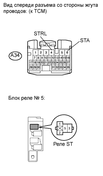
ST relay terminal 1 - A34-4 (STRL)
| Always
| Below 1 Ω
|
ST relay terminal 1 - A34-6 (STA)
| Always
| Below 1 Ω
|
- Standard resistance (check for short):
Tester Connection
| Condition
| Specified Condition
|
ST relay terminal 1, A34-4 (STRL) or A34-6 (STA) - Body ground
| Always
| 10 kΩ or higher
|
Reinstall the ST relay.
Reconnect the TCM and ECM connector.
| | REPAIR OR REPLACE HARNESS OR CONNECTOR |
|
|
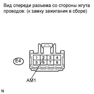
| 6.CHECK HARNESS AND CONNECTOR (IGNITION SWITCH - BATTERY) |
Disconnect the ignition switch connector.
Measure the voltage according to the value(s) in the table below.
- Standard voltage:
Tester Connection
| Condition
| Specified Condition
|
E4-2 (AM1) - Body ground
| Always
| 11 to 14 V
|
Reconnect the ignition switch connector.
| | REPAIR OR REPLACE HARNESS OR CONNECTOR |
|
|
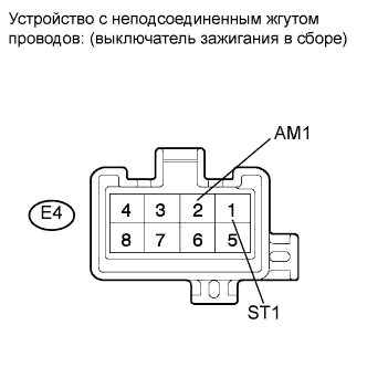
| 7.INSPECT IGNITION SWITCH ASSEMBLY |
Disconnect the ignition switch connector.
Measure the resistance according to the value(s) in the table below.
- Standard resistance:
Tester Connection
| Switch Condition
| Specified Condition
|
All terminals
| LOCK
| 10 kΩ or higher
|
E4-2 (AM1) - E4-1 (ST1)
| START
| Below 1 Ω
|
Reconnect the ignition switch connector.
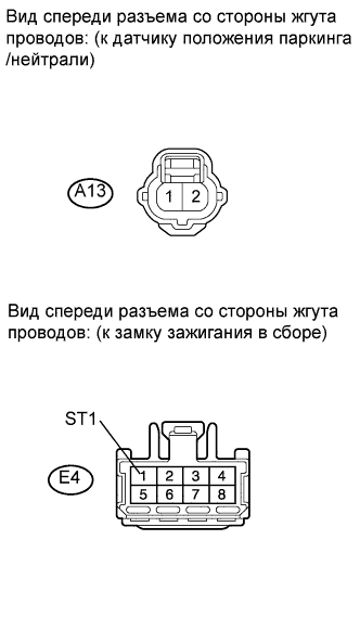
| 8.CHECK HARNESS AND CONNECTOR (IGNITION SWITCH - PARK/NEUTRAL POSITION SWITCH) |
Disconnect the park/neutral position switch connector.
Disconnect the ignition switch connector.
Measure the resistance according to the value(s) in the table below.
- Standard resistance (check for open):
Tester Connection
| Condition
| Specified Condition
|
A13-2 - E4-1 (ST1)
| Always
| Below 1 Ω
|
- Standard resistance (check for short):
Tester Connection
| Condition
| Specified Condition
|
A13-2 or E4-1 (ST1) - Body ground
| Always
| 10 kΩ or higher
|
Reconnect the park/neutral position switch connector.
Reconnect the ignition switch connector.
| | REPAIR OR REPLACE HARNESS OR CONNECTOR |
|
|
| 9.INSPECT PARK/NEUTRAL POSITION SWITCH |
Inspect the park/neutral position switch assembly (See page Нажмите здесь).
| 10.CHECK HARNESS AND CONNECTOR (TCM - PARK/NEUTRAL POSITION SWITCH) |
Disconnect the TCM connector.
Disconnect the park/neutral position switch connector.
Measure the resistance according to the value(s) in the table below.
- Standard resistance (check for open):
Tester Connection
| Condition
| Specified Condition
|
A13-1 - A34-3 (TMN)
| Always
| Below 1 Ω
|
- Standard resistance (check for short):
Tester Connection
| Condition
| Specified Condition
|
A13-1 or A34-3 (TMN) - Body ground
| Always
| 10 kΩ or higher
|
Reconnect the TCM connector.
Reconnect the park/neutral position switch connector.
| | REPAIR OR REPLACE HARNESS OR CONNECTOR |
|
|
| OK |
|
|
|
| PROCEED TO NEXT CIRCUIT INSPECTION SHOWN IN PROBLEM SYMPTOMS TABLE |
|