Двигатель. COROLLA, AURIS. ZZE150 ZRE151,152 NDE150
DESCRIPTION
WIRING DIAGRAM
INSPECTION PROCEDURE
CHECK ENTRY FUNCTION DETECTION AREA
CHECK IF ENGINE STARTS (INITIALIZE STEERING LOCK)
CHECK FOR DTC
CHECK ENGINE SWITCH CONDITION
CHECK CRANKING FUNCTION
READ VALUE OF INTELLIGENT TESTER (PARK/NEUTRAL POSITION SWITCH)
INSPECT PARK/NEUTRAL POSITION SWITCH
CHECK HARNESS AND CONNECTOR (PARK/NEUTRAL POSITION SWITCH - MAIN BODY ECU, ECM)
READ VALUE OF INTELLIGENT TESTER (CLUTCH PEDAL SWITCH)
INSPECT CLUTCH PEDAL SWITCH
CHECK HARNESS AND CONNECTOR (CLUTCH PEDAL SWITCH - MAIN BODY ECU, ECM)
READ VALUE OF INTELLIGENT TESTER (STOP LIGHT SWITCH)
READ VALUE OF INTELLIGENT TESTER (STEERING LOCK)
CHECK STEERING LOCK
INSPECT MAIN BODY ECU (STSW VOLTAGE)
INSPECT ECM (ACCR VOLTAGE)
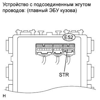
INSPECT MAIN BODY ECU (STR VOLTAGE)
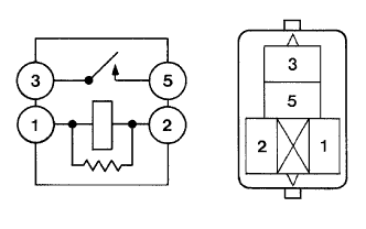
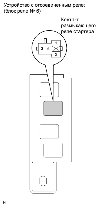
INSPECT RELAY (STARTER CUT RELAY)
INSPECT ECM (STR2 VOLTAGE)
CHECK HARNESS AND CONNECTOR (MAIN BODY ECU - ECM - RELAY BLOCK NO. 6)
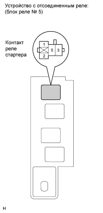
INSPECT RELAY (STARTER RELAY)
CHECK HARNESS AND CONNECTOR (ECM - STARTER RELAY)
INSPECT RELAY BLOCK NO. 5 (STARTER RELAY VOLTAGE)
INSPECT STARTER ASSEMBLY
READ VALUE OF INTELLIGENT TESTER (L CODE)
READ VALUE OF INTELLIGENT TESTER (ENGINE START REQUEST)
READ VALUE OF INTELLIGENT TESTER (S CODE)
INSPECT ID CODE BOX
REPLACE CERTIFICATION ECU
СИСТЕМА ПОСАДКИ И ЗАПУСКА - Двигатель не запускается |
DESCRIPTION
| ENGINE START SYSTEM FUNCTION |
for AT: If the engine switch is pressed with the shift lever in the P or N position and the brake pedal depressed, the main body ECU determines that it is an engine start request.
for MT: If the engine switch is pressed with the clutch pedal depressed, the main body ECU determines that it is an engine start request.
The certification ECU and other ECUs perform key verification via the LIN communication line.
The main body ECU activates the ACC relay.
The main body ECU activates the IG1 and IG2 relays.
The certification ECU outputs a steering UNLOCK signal. The signal is sent to the main body ECU via the steering lock ECU.
The main body ECU sends an engine start request signal to the ECM.
The ECM sends an ACC cut request signal to the main body ECU.
The ECM and main body ECU activate the starter relay.
The main body ECU deactivates the ACC relay until the ECU detects an engine start.
When engine revolution speed reaches 1200 rpm, the ECM determines that the engine has been started.
The ECM stops sending on ACC cut request signal to the main body ECU.
The main body ECU reactivates the ACC relay and turns off the engine switch indicator light, when engine revolution speed reaches 800 rpm.
Symbols of main body ECU
| Signals
|
STP
| Stop light switch ON signal
| Input
|
SSW1/SSW2
| Engine switch ON signal
| Input
|
ACCD
| ACC relay operation signal
| Output
|
SLP
| Steering lock actuator position signal
| Input
|
IG1D
| IG1 relay operation signal
| Output
|
IG2D
| IG2 relay operation signal
| Output
|
STR2
| Starter relay operation signal (Sub)
| Output
|
STR
| Park/Neutral position switch signal / Clutch pedal switch signal
| Input
|
TACH
| Engine start detection signal
| Input
|
STSW
| Starter activation request signal
| Output
|
ACCR
| ACC cut request signal
| Input
|
Symbols of ECM
| Signals
|
ACCR
| ACC cut request signal
| Output
|
TACH
| Engine revolution speed signal
| Output
|
STSW
| Starter activation request signal
| Input
|
STAR
| Starter relay operation signal (Main)
| Output
|
STA
| Starter activation signal
| Input
|
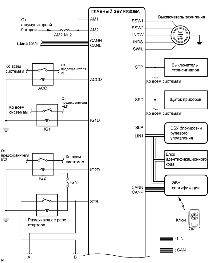
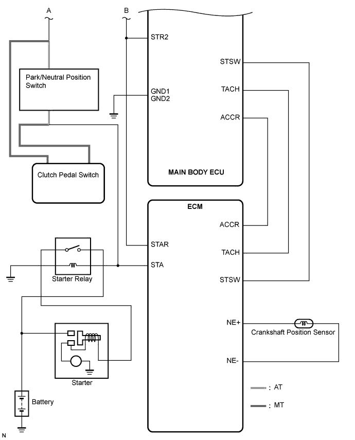
WIRING DIAGRAM
See CRANKING HOLDING FUNCTION CIRCUIT (See page Нажмите здесь).
INSPECTION PROCEDURE
| EMERGENCY ENGINE START CONTROL |
for AT: If there is a malfunction in the stop light switch or STOP fuse, their signals may not be correctly transmitted to the main body ECU. This may result in the engine not starting even if the engine switch is pressed while the brake pedal is depressed and the shift lever is in the P position.
To activate the starter:
Turn the engine switch from off to on (ACC).
Press and hold the engine switch for 15 seconds.
- УКАЗАНИЕ:
- After the main body ECU, certification ECU, steering lock ECU, ID code box and/or ECM are/is replaced, perform the registration procedures for the engine immobiliser system.
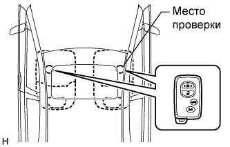
| 1.CHECK ENTRY FUNCTION DETECTION AREA |
Inspect entry detection area.
for AT:
When the electrical key is in either of the 2 inspection points in the illustration, the shift lever is in the P position and the brake pedal is depressed, check that the engine switch indicator illuminates in green.
for MT:
When the electrical key is in either of the 2 inspection points in the illustration, the clutch pedal is depressed, check that the engine switch indicator illuminates in green.
- OK:
- Engine switch illuminates in green.
- УКАЗАНИЕ:
- If the engine switch does not illuminate, perform troubleshooting according to PROBLEM SYMPTOMS TABLE of the entry and start system (starting) (engine switch indicator light does not come on) (See page Нажмите здесь) and the entry and start system (entry door lock) (room oscillator does not recognize key) (for Sedan: See page Нажмите здесь) (for Hatchback: See page Нажмите здесь).
| 2.CHECK IF ENGINE STARTS (INITIALIZE STEERING LOCK) |
Turn the engine switch off.
for AT:
Make sure that the shift lever is in the P position.
for MT:
When the clutch pedal is depressed, check if the engine can be started.
Open and close the driver's door.
for AT:
When the shift lever is in the P position and the brake pedal is depressed, check if the engine can be started.
for MT:
When the clutch pedal is depressed, check if the engine can be started.
- OK:
- Steering lock/unlock function operates normally and engine can be started.
- УКАЗАНИЕ:
- After the battery is discharged and then recharged, the engine may not start unless the steering lock is initialized using the above procedure (See page Нажмите здесь).
Delete the DTCs (See page Нажмите здесь).
Check for DTCs again.
- OK:
- No DTC is output.
- УКАЗАНИЕ:
- If entry and start system (starting function) DTCs are output (See page Нажмите здесь).
- If electrical steering lock DTCs are output (See page Нажмите здесь).
- If engine immobiliser system DTCs are output (See page Нажмите здесь).
- If engine control system DTCs output (2ZR-FE) (See page Нажмите здесь).
| 4.CHECK ENGINE SWITCH CONDITION |
Check the power source mode changes.
for AT:
When the key is inside the vehicle and the shift lever is in the P position, check that pressing the engine switch causes the power source mode to change as follows:
for MT:
When the key is inside the vehicle, check that pressing the engine switch causes the power source mode to change as follows:
- OK:
- off → on (ACC) → on (IG) → off
- УКАЗАНИЕ:
- If power source mode does not change to ON (IG and ACC) (See page Нажмите здесь).
- If power source mode does not change to ON (IG) (See page Нажмите здесь).
- If power source mode does not change to ON (ACC) (See page Нажмите здесь).
| 5.CHECK CRANKING FUNCTION |
Check the engine cranking function.
for AT:
When there is fuel in the fuel tank, the key is inside the vehicle, and the shift lever is in the P position, check that depressing the brake pedal and pressing the engine switch crank the engine.
for MT:
When there is fuel in the fuel tank, the key is inside the vehicle, check that depressing the clutch pedal and pressing the engine switch crank the engine.
- Result:
Result
| Proceed to
|
Engine does not crank (AT)
| A
|
Engine does not crank (MT)
| B
|
Engine cranks
| C
|
| 6.READ VALUE OF INTELLIGENT TESTER (PARK/NEUTRAL POSITION SWITCH) |
Connect the intelligent tester to the DLC3.
Turn the engine switch on (IG)
Read the DATA LIST according to the displays on the tester screen.
Body:Tester Display
| Measurement Item/Range
| Normal Condition
| Diagnostic Note
|
N SW / C SW
| Park/Neutral position switch / ON or OFF
| ON: Shift position is N
OFF: Shift position is not N
| -
|
- OK:
- ON (Shift position is N) and OFF (Shift position is not N) appear on the screen.
Proceed to the next step based on the inspection result.
- Result:
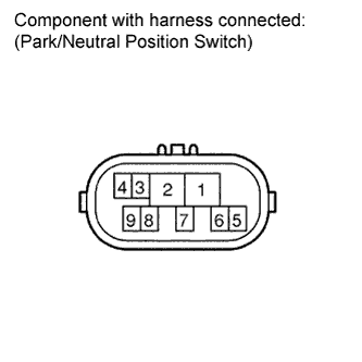
| 7.INSPECT PARK/NEUTRAL POSITION SWITCH |
Disconnect the park/neutral position (PNP) switch connector.
Measure the resistance according to the value(s) in the table below.
- Standard resistance:
Tester Connection
| Condition
| Specified Condition
|
4 - 5
| P
| Below 1 Ω
|
4 - 5
| N
| Below 1 Ω
|
4 - 5
| Except P and N
| 10 kΩ or higher
|
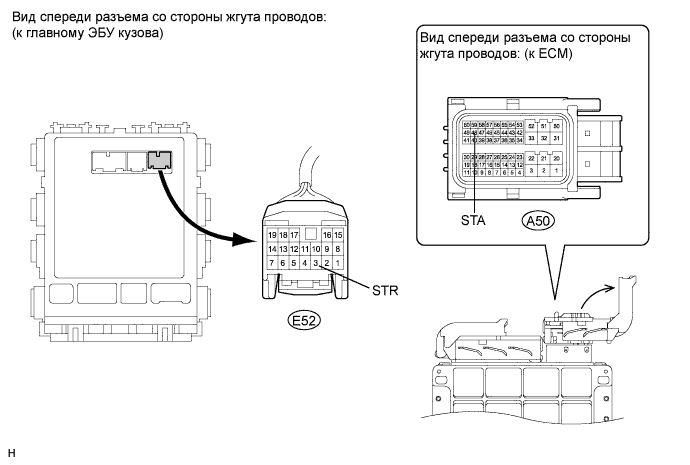
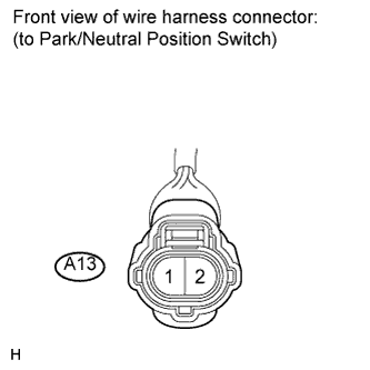
| 8.CHECK HARNESS AND CONNECTOR (PARK/NEUTRAL POSITION SWITCH - MAIN BODY ECU, ECM) |
Disconnect the E52 ECU connector.
Disconnect the A50 ECM connector.
Disconnect the A13 park/neutral position switch connector.
Measure the resistance according to the value(s) in the table below.
- Standard resistance:
Tester Connection
| Condition
| Specified Condition
|
E52-3 (STR) - A13-2
| Always
| Below 1Ω
|
A50-48 (STA) - A13-1
|
E52-3 (STR) - Body ground
| 10 kΩ or higher
|
A50-48 (STA) - Body ground
|
| | REPAIR OR REPLACE HARNESS OR CONNECTOR |
|
|
| OK |
|
|
|
| REPLACE MAIN BODY ECU (INSTRUMENT PANEL JUNCTION BLOCK) |
|
| 9.READ VALUE OF INTELLIGENT TESTER (CLUTCH PEDAL SWITCH) |
Connect the intelligent tester to the DLC3.
Turn the engine switch on (IG).
Read the DATA LIST according to the displays on the tester screen.
Body:Tester Display
| Measurement Item/Range
| Normal Condition
| Diagnostic Note
|
N SW / C SW
| Clutch pedal switch / ON or OFF
| ON: Clutch pedal depressed
OFF: Clutch pedal released
| -
|
- OK:
- ON (Clutch pedal depressed) and OFF (Clutch pedal released)
Proceed to the next step based on the inspection result.
- Result:
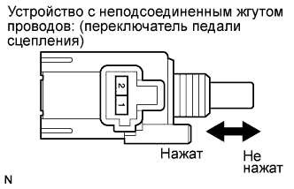
| 10.INSPECT CLUTCH PEDAL SWITCH |
Remove the clutch pedal switch (See page Нажмите здесь).
Measure the resistance according to the value(s) in the table below.
- Standard resistance:
Tester Connection
| Condition
| Specified Condition
|
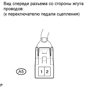
A5-1 - A5-2
| Pushed in
| Below 1 Ω
|
Free
| 10 kΩ or higher
|
A5-1 - Body ground
| Always
| 10 kΩ or higher
|
| 11.CHECK HARNESS AND CONNECTOR (CLUTCH PEDAL SWITCH - MAIN BODY ECU, ECM) |
Remain the E52 ECU and A50 ECM connectors still disconnected.
Disconnect the A5 clutch pedal switch connector.
Measure the resistance according to the value(s) in the table below.
- Standard resistance:
Tester Connection
| Condition
| Specified Condition
|
A5-2 - E52-3 (STR)
| Always
| Below 1 Ω
|
A5-2 - Body ground
| 10 kΩ or higher
|
A50-48 (STA) - A5-1
| Below 1 Ω
|
A5-1 - Body ground
| 10 kΩ or higher
|
| | REPAIR OR REPLACE HARNESS OR CONNECTOR |
|
|
| OK |
|
|
|
| REPLACE MAIN BODY ECU (INSTRUMENT PANEL JUNCTION BLOCK) |
|
| 12.READ VALUE OF INTELLIGENT TESTER (STOP LIGHT SWITCH) |
Connect the intelligent tester to the DLC3.
Turn the engine switch on (IG).
Read the DATA LIST according to the displays on the tester screen.
Body:Tester Display
| Measurement Item/Range
| Normal Condition
| Diagnostic Note
|
Stop Light SW
| Stop Light Switch /ON or OFF
| ON: Brake pedal depressed
OFF: Brake pedal released
| -
|
- OK:
- ON (brake pedal depressed) and OFF (brake pedal released) appear on the screen.
- УКАЗАНИЕ:
- If the result is not as specified, perform troubleshooting for DTC B2284 (Brake signal malfunction) first.
| 13.READ VALUE OF INTELLIGENT TESTER (STEERING LOCK) |
Connect the intelligent tester to the DLC3.
Turn the engine switch on (IG).
Body:Tester Display
| Measurement Item/Range
| Normal Condition
| Diagnostic Note
|
Str Unlock SW
| Steering lock condition / ON or OFF
| ON: Steering is unlocked (Engine switch on (ACC))
OFF: Steering is locked (Engine switch off)
| -
|
- OK:
- ON (steering is unlocked) and OFF (steering is locked) appear on the screen.
- УКАЗАНИЕ:
- If the result is not as specified, perform troubleshooting for DTCs B2285 (Steering lock position signal circuit malfunction) (See page Нажмите здесь) and B2288 (Steering lock signal circuit malfunction) first (See page Нажмите здесь).
Check if the steering lock is released when turning the engine switch on (ACC).
- OK:
- The steering lock is released.
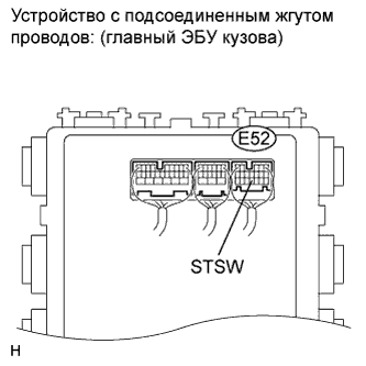
| 15.INSPECT MAIN BODY ECU (STSW VOLTAGE) |
Reconnect the E52 ECU connector.
Measure the voltage according to the value(s) in the table below.
- Standard voltage:
Tester Connection
| Condition
| Specified Condition
|
E52-4 (STSW) - Body ground
| Brake pedal depressed, engine witch held on (ST)*1
Clutch pedal depressed, engine switch held on (ST)*2
| Output voltage at terminal AM1 or AM2 is 2 V or more.
|
*1: AT
*2: MT
- УКАЗАНИЕ:
- If the result is not as specified, perform troubleshooting for DTC B2275 (STSW monitor malfunction) first.
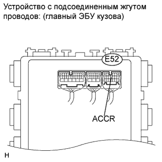
| 16.INSPECT ECM (ACCR VOLTAGE) |
Measure the voltage according to the value(s) in the table below.
- Standard voltage:
Tester Connection
| Condition
| Specified Condition
|
E52-11 (ACCR) - Body ground
| Brake pedal depressed, shift lever P position, engine switch is pushed once → on (IG)*1
Clutch pedal depressed, engine switch is pushed once → on (IG)*2
| 0.1 to 0.8*3 → Output voltage at terminal AM1 or AM2 is -2 V or more.
|
*1: AT
*2: MT
*3: Voltage is output only when the engine is cranking.
- УКАЗАНИЕ:
- If the result is not as specified, perform troubleshooting for DTC B2276 (ACCR signal circuit malfunction) first.
| 17.INSPECT MAIN BODY ECU (STR VOLTAGE) |
Measure the voltage according to the value(s) in the table below.
- Standard voltage:
Tester Connection
| Condition
| Specified Condition
|
E52-3 (STR) - Body ground
| Shift lever P position → except P position*1
Clutch pedal depressed → Clutch pedal released*2
| Below 2 V → Pulse generation
|
*1: AT
*2: MT
Proceed to the next step based on the inspection result.
- Result:
| 18.INSPECT RELAY (STARTER CUT RELAY) |
Remove the starter cut relay.
Measure the resistance according to the value(s) in the table below.
- Standard resistance:
Tester Connection
| Condition
| Specified Condition
|
3 -5
| When battery voltage is not applied to terminals 1 and 2
| 10 kΩ or higher
|
3 - 5
| When battery voltage is applied to terminals 1 and 2
| Below 1 Ω
|
| | REPLACE STARTER CUT RELAY |
|
|
| 19.INSPECT ECM (STR2 VOLTAGE) |
Disconnect the B31 ECM connector.
Measure the voltage according to the value(s) in the table below.
- Standard voltage:
Tester Connection
| Condition
| Specified Condition
|
E52-14 (STR2) - Body ground
| Brake pedal depressed, shift lever P position, engine switch on (ST)*1
Clutch pedal depressed, engine switch on (ST)*2
| Output voltage at terminal AM1 or AM2 is -3.5 V or more*3
|
*1: AT
*2: MT
*3: Voltage is output for 0.3 seconds when the engine is cracking to start. Disconnect the B31 connector from the ECM before measuring the voltage.
| | REPLACE MAIN BODY ECU (INSTRUMENT PANEL JUNCTION BLOCK) |
|
|
| 20.CHECK HARNESS AND CONNECTOR (MAIN BODY ECU - ECM - RELAY BLOCK NO. 6) |
Disconnect the E52 ECU connector.
Disconnect the B31 ECM connector.
Measure the resistance according to the value(s) in the table below.
- Standard resistance:
Tester Connection
| Condition
| Specified Condition
|
E52-14 (STR2) - B31-52 (STAR)
| Always
| Below 1 Ω
|
E52-14 (STR2) - Starter cut relay terminal-3
|
E52-3 (STR) - Starter cut relay terminal-5
|
E52-14 (STR2) - Body ground
| 10 kΩ or higher
|
| | REPAIR OR REPLACE HARNESS OR CONNECTOR |
|
|
| 21.INSPECT RELAY (STARTER RELAY) |
Remove the starter relay from the relay block No 5.
Measure the resistance according value(s) in the table below.
- Standard resistance:
Tester Connection
| Condition
| Specified Condition
|
3 - 5
| When battery voltage is not applied to terminals 1 and 2
| 10 kΩ or higher
|
3 - 5
| When battery voltage is applied to terminals 1 and 2
| Below 1 Ω
|
| 22.CHECK HARNESS AND CONNECTOR (ECM - STARTER RELAY) |
Disconnect the A50 ECM connector.
Measure the resistance according to the value(s) in the table below.
- Standard resistance:
Tester Connection
| Condition
| Specified Condition
|
A50-48 (STA) - Starter relay terminal-1
| Always
| Below 1 Ω
|
A50-48 (STA) - Body ground
| 10 kΩ or higher
|
| | REPAIR OR REPLACE HARNESS OR CONNECTOR |
|
|
| 23.INSPECT RELAY BLOCK NO. 5 (STARTER RELAY VOLTAGE) |
Measure the voltage according to the value(s) in the table below.
- Standard voltage:
Tester Connection
| Condition
| Specified Condition
|
Starter relay terminal-5 - Body ground
| Always
| 11 to 14 V
|
Starter relay terminal-2 - Body ground
| Below 1 V
|
| | REPAIR OR REPLACE HARNESS OR CONNECTOR (STARTER - BATTERY, STARTER RELAY) |
|
|
| 24.INSPECT STARTER ASSEMBLY |
- УКАЗАНИЕ:
- (See page Нажмите здесь).
| | REPAIR OR REPLACE STARTER ASSEMBLY |
|
|
| OK |
|
|
|
| REPAIR OR REPLACE HARNESS OR CONNECTOR (STARTER - BATTERY, STARTER RELAY) |
|
| 25.READ VALUE OF INTELLIGENT TESTER (L CODE) |
Reconnect the connectors.
Connect the intelligent tester to the DLC3.
- УКАЗАНИЕ:
- When using the intelligent tester with the engine switch off, turn on and off any of the door courtesy light switches repeatedly at 1.5 second intervals or less until communication between the tester and vehicle starts.
Turn the engine switch on (IG).
Entry & Start (Certification ECU):Tester Display
| Measurement Item/Range
| Normal Condition
| Diagnostic Note
|
L Code Chk
| L code check / OK or NG
| OK: Normal
NG: Malfunction
| Electrical key in the cabin
|
- OK:
- OK is displayed on the screen.
- УКАЗАНИЕ:
- If the result is not as specified, refer to PROBLEM SYMPTOMS TABLE of the electrical steering lock (steering wheel cannot be unlocked) (See page Нажмите здесь).
- If the result is not as specified, there may be a malfunction with the steering lock ECU or the ID code box.
| | GO TO ELECTRIC STEERING LOCK |
|
|
| 26.READ VALUE OF INTELLIGENT TESTER (ENGINE START REQUEST) |
Connect the intelligent tester to the DLC3.
- УКАЗАНИЕ:
- When using the intelligent tester with the engine switch off, turn on and off any of the door courtesy light switches repeatedly at 1.5 second intervals or less until communication between the tester and vehicle starts.
Turn the engine switch on (IG)
Entry & Start (Certification ECU):Tester Display
| Measurement Item/Range
| Normal Condition
| Diagnostic Note
|
Start Rqst
| Start request signal response / OK or NG
| OK: Received
NG: Not received
| -
|
- OK:
- OK (received) and NG (not receive) appear on the screen.
- УКАЗАНИЕ:
- If the result is not as specified, there may be a malfunction with the certification ECU or the ID code box.
| | REPLACE CERTIFICATION ECU |
|
|
| 27.READ VALUE OF INTELLIGENT TESTER (S CODE) |
Connect the intelligent tester to the DLC3.
- УКАЗАНИЕ:
- When using the intelligent tester with the engine switch off, turn on and off any of the door courtesy light switches repeatedly at 1.5 second intervals or less until communication between the tester and vehicle starts.
Turn the engine switch on (IG).
Entry & Start (Certification ECU):Tester Display
| Measurement Item/Range
| Normal Condition
| Diagnostic Note
|
S Code Chk
| S code check / OK or NG
| OK: Normal
OFF: Malfunction
| -
|
- OK:
- OK is displayed on the screen.
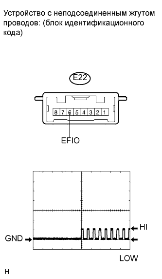
Check the input signal waveform.
Connect an oscilloscope to terminal E22-6 (EFIO) and body ground.
Turn the engine switch on (IG).
Check the signal waveform according to the condition(s) in the table below.
Item
| Condition
|
Tool setting
| 10 V/DIV., 100 ms./ DIV.
|
Vehicle condition
| Engine switch on (IG)
|
| 29.REPLACE CERTIFICATION ECU |
Replace the certification ECU.
Perform the registration procedures for the engine immobiliser system.
Check if the engine can be started.
| OK |
|
|
|
| END (CERTIFICATION ECU IS DEFECTIVE) |
|