Dtc B2278 Engine Switch Circuit Malfunction. Corolla Auris
Двигатель. COROLLA, AURIS. ZZE150 ZRE151,152 NDE150
DESCRIPTION
WIRING DIAGRAM
INSPECTION PROCEDURE
READ VALUE OF INTELLIGENT TESTER (START SWITCH)
CHECK ENGINE SWITCH CONDITION
INSPECT ENGINE SWITCH
CHECK HARNESS AND CONNECTOR (ENGINE SWITCH - MAIN BODY ECU AND BODY GROUND)
DTC B2278 Engine Switch Circuit Malfunction |
DESCRIPTION
This DTC is output when 1) a malfunction is detected between the main body ECU and the engine switch; or 2) either of the switches inside the engine switch is malfunctioning.- УКАЗАНИЕ:
- When the main body ECU is replaced with a new one and the negative (-) battery terminal is connected, the power source mode becomes the IG-ON mode. When the battery is removed and reinstalled, the power source mode that was selected when the battery was removed is restored.
After the main body ECU is replaced, perform the registration procedures for the engine immobiliser system.DTC No.
| DTC Detection Condition
| Trouble Area
|
B2278
| Communication is abnormal between the main body ECU and engine switch or the engine switch is defective
| - Engine switch
- Main body ECU
- Wire harness or connector
|
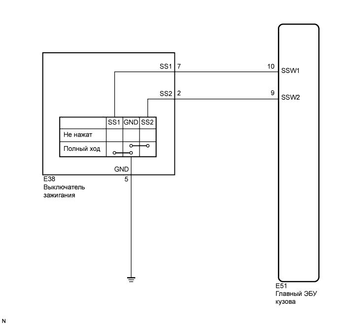
WIRING DIAGRAM
INSPECTION PROCEDURE
| 1.READ VALUE OF INTELLIGENT TESTER (START SWITCH) |
Connect the intelligent tester to the DLC3.
Check the DATA LIST for proper functioning of the start switch.
- УКАЗАНИЕ:
- When using the intelligent tester with the engine switch off, turn on and off any of the door courtesy light switches repeatedly at 1.5 second intervals or less until communication between the tester and vehicle starts.
Body:Tester Display
| Measurement Item/Range
| Normal Condition
| Diagnostic Note
|
St SW1
| Start Switch 1 / ON or OFF
| ON: Engine switch is pushed
OFF: Engine switch is not pushed
| -
|
St SW2
| Start Switch 2 / ON or OFF
| ON: Engine switch is pushed
OFF: Engine switch is not pushed
| -
|
- OK:
- ON (engine switch is pushed) and OFF (engine switch is not pushed) appear on the screen.
| 2.CHECK ENGINE SWITCH CONDITION |
Check the power source mode changes.
When the key is inside the vehicle, check that pressing the engine switch causes the power source mode to change as follows:
- OK:
- off → on (ACC) → on (IG) → off
- УКАЗАНИЕ:
- If power source mode does not change to ON (IG and ACC) (See page Нажмите здесь).
- If power source mode does not change to ON (IG) (See page Нажмите здесь).
- If power source mode does not change to ON (ACC) (See page Нажмите здесь).
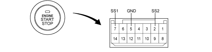
Remove the engine switch (See page Нажмите здесь).
Disconnect the switch connector.
Measure the resistance according to the value(s) in the table below.
- Standard resistance:
Tester Connection
| Switch Condition
| Specified Condition
|
7 (SS1) - 5 (GND)
| Pushed
| Below 1 Ω
|
2 (SS2) - 5 (GND)
| Pushed
| Below 1 Ω
|
7 (SS1) - 5 (GND)
| Not pushed
| 10 kΩ or higher
|
2 (SS2) - 5 (GND)
| Not pushed
| 10 kΩ or higher
|
- УКАЗАНИЕ:
- This switch is a momentary type switch.
| 4.CHECK HARNESS AND CONNECTOR (ENGINE SWITCH - MAIN BODY ECU AND BODY GROUND) |
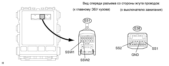
Disconnect the E51 ECU connector.
Measure the resistance according to the value(s) in the table below.
- Standard resistance:
Tester Connection
| Condition
| Specified Condition
|
E38-7 (SS1) - E51-10 (SSW1)
| Always
| Below 1 Ω
|
E38-2 (SS2) - E51-9 (SSW2)
| Always
| Below 1 Ω
|
E38-5 (GND) - Body ground
| Always
| Below 1 Ω
|
E38-7 (SS1) or E51-10 (SSW1) - Body ground
| Always
| 10 kΩ or higher
|
E38-2 (SS2) or E51-9 (SSW2) - Body ground
| Always
| 10 kΩ or higher
|
| | REPAIR OR REPLACE HARNESS OR CONNECTOR |
|
|
| OK |
|
|
|
| REPLACE MAIN BODY ECU (INSTRUMENT PANEL JUNCTION BLOCK) |
|