Система Ecd -- Описание Системы |
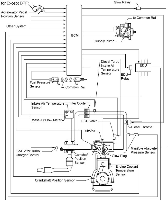
| ENGINE CONTROL SYSTEM |
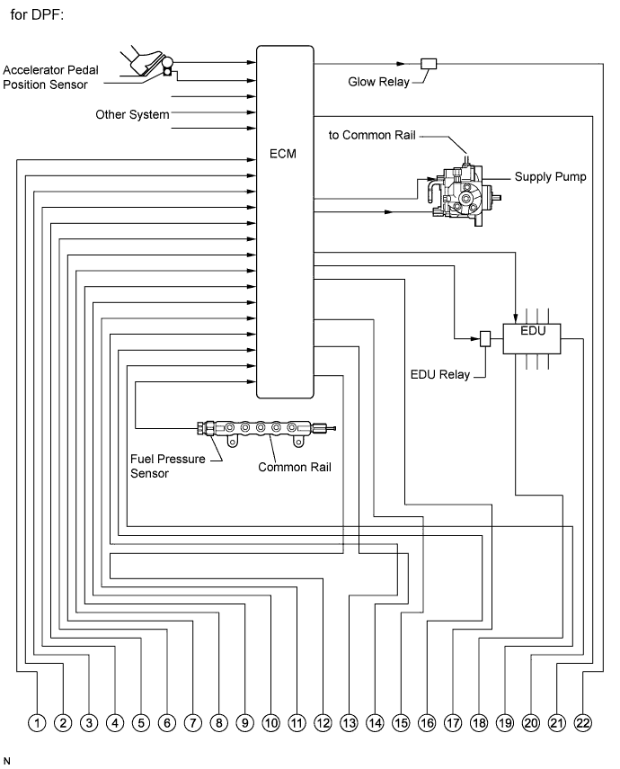
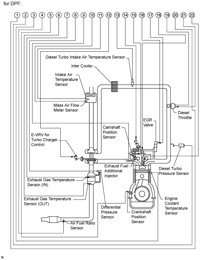
| DPF DESCRIPTION |
Diesel Particulate Filter (DPF) System comprehensively regulates engine control (consists of a catalytic system and a fuel injection system) that purifies particulate matter (PM) by diesel engines. The catalytic system purifies hydrocarbons (HC) and carbon monoxides (CO), and reduces PM with a catalytic converter with the diesel particulate filter. The fuel injection system adds fuel into the exhaust port using the exhaust fuel addition injector to produce maintain a proper catalyst temperature for DPF catalyst regeneration.
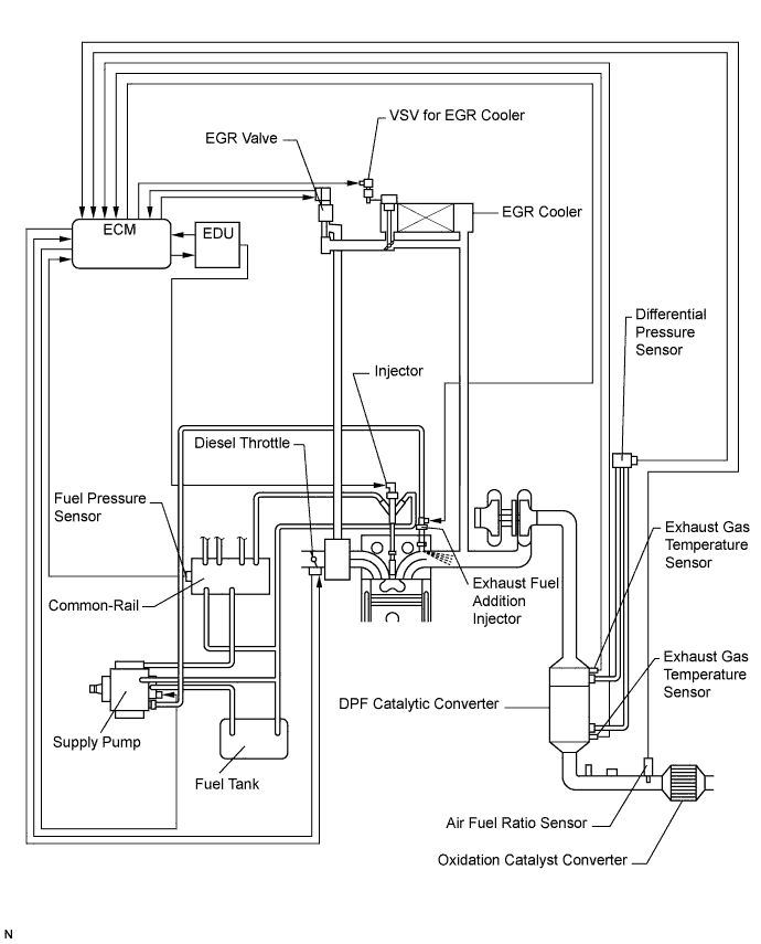
DPF components:
Component Description DPF catalytic converter Reduces HC, CO, and PM. Exhaust fuel addition injector Adds fuel into the exhaust port in order to raise the catalyst temperature and combust PM. Exhaust gas temperature sensor Used for estimating DPF catalytic converter temperature and adjusting fuel addition by ECM while DPF catalyst regeneration is performed. Also, detects DPF catalytic converter temperature to prevent the catalytic converter temperature from rising too high. Differential pressure sensor Detects the volume of PM deposits and incorrect vacuum hose arrangement on the DPF catalytic converter. Air fuel ratio sensor Used for controlling air fuel ratio. By controlling the air fuel ratio, combustion control for low temperature combustion and DPF catalyst regeneration are properly regulated. Diagnostics Trouble Codes (DTCs) table for DPF:
- УКАЗАНИЕ:
- This table indicates typical DTC combinations for each malfunction occurrence.
*: There may be no DTC output depending on the condition of the malfunction.Trouble Area Malfunction DTC No. DPF catalytic converter Deteriorated or clogged P2002, P1601, P1386* Exhaust fuel addition injector Stuck open P1386 Stuck closed P1386, P2002* Low fuel addition volume P1386, P2002* Open in exhaust fuel addition injector circuit P1386, P2047, P2002* Short in exhaust fuel addition injector circuit P1386, P2047 Open or short in exhaust fuel addition injector P1386, P2047, P2002* Exhaust gas temperature sensor Open in exhaust gas temperature sensor circuit P0544, P0545, P0546, P1386, P2031, P2032, P2033 Short in exhaust gas temperature sensor circuit P0544, P0545, P0546, P1386*, P2002*, P2031, P2032, P2033 Exhaust gas temperature sensor P0544, P0545, P0546, P1386*, P2031, P2032, P2033 Differential pressure sensor Open in differential pressure sensor circuit P1425, P1427, P1428, P2002* Short in differential pressure sensor circuit P1425, P1427, P1428, P2002* Differential pressure sensor P1425, P1427, P1428, P2002* Differential pressure sensor clogged P1426, P2002* Incorrect vacuum hose arrangement of the differential pressure sensor P1426, P2002* Air fuel ratio sensor Open or short in air fuel ratio sensor or heater circuit P0031, P0032, P1386*, P2238, P2239, P2252, P2253 Air fuel ratio sensor P0031, P0032, P1386*, P2238, P2239, P2252, P2253 Exhaust gas leaks Exhaust gas leaks P1386*, P2002* Fuel leaks Fuel leaks in fuel addition injector P1386* Supply pump Correct fuel pressure cannot be fed to the exhaust fuel addition injector P1386* Diagnostics trouble code description for DPF:
DTC No. Description P0031 Open or short in air fuel ratio sensor heater control circuit (Low output) P0032 Open or short in air fuel ratio sensor heater control circuit (High output) P0544 Open or short in exhaust gas temperature sensor circuit (Upstream) P0545 Open or short in exhaust gas temperature sensor circuit (Upstream) (Low output) P0546 Open or short in exhaust gas temperature sensor circuit (Upstream) (High output) P1386 DPF fuel addition system malfunction P1425 Open or short in differential pressure sensor circuit P1426 Differential pressure sensor is clogged or has incorrect vacuum hose arrangement P1427 Open or short in differential pressure sensor circuit (Low output) P1428 Open or short in differential pressure sensor circuit (High output) P2002 DPF catalytic converter malfunction P2031 Open or short in exhaust gas temperature sensor circuit (Downstream) P2032 Open or short in exhaust gas temperature sensor circuit (Downstream) (Low output) P2033 Open or short in exhaust gas temperature sensor circuit (Downstream) (High output) P2047 Open in exhaust fuel addition injector circuit P2048 Open in exhaust fuel addition injector circuit P2049 Open in exhaust fuel addition injector circuit P2238 Open or short in air fuel ratio sensor circuit (Low output) P2239 Open or short in air fuel ratio sensor circuit (High output) P2252 Open or short in air fuel ratio sensor circuit (Low output) P2253 Open or short in air fuel ratio sensor circuit (High output)
| COMMON RAIL SYSTEM DESCRIPTION |
Common rail system:
The common rail system uses high-pressurized fuel for improved fuel economy and to provide robust engine power, while suppressing engine vibration and noise.
This system stores fuel, which has been pressurized and supplied by the supply pump, in the common rail. By storing fuel at high-pressure, the common rail system can provide fuel at stable fuel injection pressures, regardless of engine speed or engine load.
The ECM provides an electric current to the solenoid valve in the injector, using the EDU, to regulate the fuel injection timing and volume, and also monitors the internal fuel pressure of the common rail using the fuel pressure sensor. The ECM causes the supply pump to supply the fuel necessary to obtain the target fuel pressure.
In addition, this system uses the 2-Way Valve (TWV) inside the injector to open and close the fuel passage. Therefore, both fuel injection time and fuel injection volume can be precisely regulated by the ECM.
The common rail system provides two split fuel injections. In order to soften combustion shock, this system performs "pilot-injection" as the subsidiary fuel injection prior to the main fuel injection. This helps to reduce engine" vibration and noise.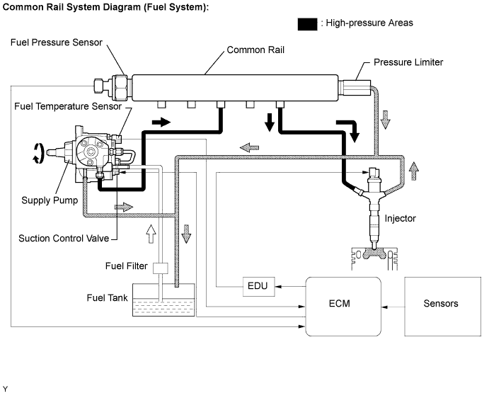
Common rail system components:
Component Description Common rail Stores high-pressure fuel produced by supply pump Supply pump Operated by crankshaft
Supplies high-pressure fuel to common railInjector Injects fuel to combustion chamber based on signals from ECM Fuel pressure sensor Monitors internal fuel pressure of common rail and sends signals to ECM Pressure limiter Opens pressure limiter to reduce internal pressure in common rail when common rail pressure exceeds specified level Suction control valve Based on signals from ECM, adjusts fuel volume supplied to common rail and regulates internal fuel pressure Diagnostic trouble codes (DTCs) table for the common rail system
- УКАЗАНИЕ:
- This table indicates typical DTC combinations for each malfunction occurrence.
*: There may be no DTC output depending on the condition of the malfunction.Trouble Area Malfunction DTC No. Injector Open or short in injector circuit P0200, P1238, P0093* Stuck open P0093, P1238 Stuck closed P1238 Fuel pressure sensor Open or short in fuel pressure sensor circuit or pressure sensor output fixed P0087, P0190, P0192, P0193 Pressure limiter Open or short in pressure limiter circuit P0088*, P0093*, P1229* Stuck open P0093 Stuck closed P0088* Suction control valve Open or short in suction control valve circuit P0627, P1229, P0088* Stuck open P1229, P0088* EDU Faulty EDU P0093*, P0200*, P1238* Common rail system (Fuel system) Fuel leaks in high-pressure area P0093 Diagnostic trouble code description for the common rail system:
DTC No. Description P0087 Fuel pressure sensor output does not change P0088 Internal fuel pressure too high (200 MPa [2039 kgf/cm2, 29007 psi] or more) P0093 Fuel leaks in high-pressure areas P0190 Open or short in fuel pressure sensor circuit (output voltage is too low or too high) P0192 Open or short in fuel pressure sensor circuit (output voltage is too low) P0193 Open or short in fuel pressure sensor circuit (output voltage is too high) P0200 Open or short in EDU or injector circuit P0627 Open or short in suction control valve circuit P1229 Fuel over-feed
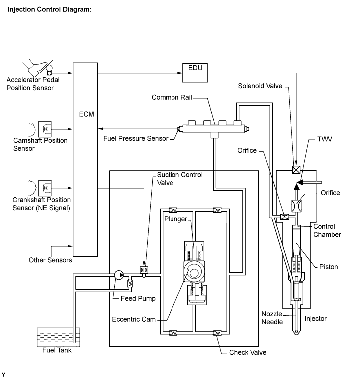
| INJECTION CONTROL SYSTEM DESCRIPTION |
The feed pump is used to pump fuel from the fuel tank to the supply pump.
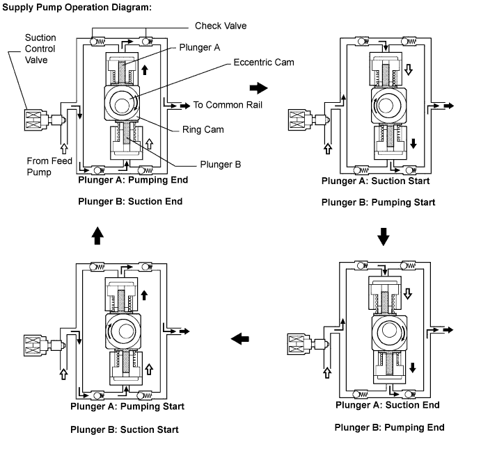
| SUPPLY PUMP OPERATION SYSTEM DESCRIPTION |
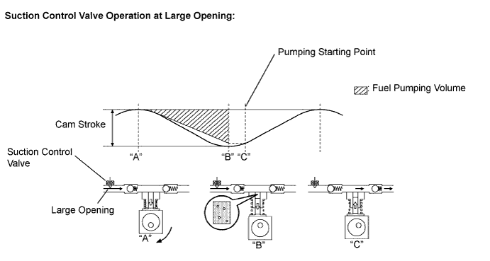
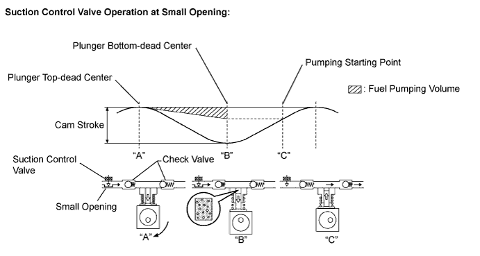
| SUCTION CONTROL VALVE OPERATION SYSTEM DESCRIPTION |
- УКАЗАНИЕ:
- The ECM controls the suction control valve operation to regulate the fuel volume that is produced by the supply pump for the common rail. This control is performed to regulate the internal fuel pressure of the common rail to the targeted injection pressure.
Small opening of the suction control valve:
When the opening of the suction control valve is small, the volume of supplied fuel is small "A".
The suction volume becomes small due to the narrow path despite the plunger stroke being full. The difference between the geometrical volume and suction volume creates a vacuum "B".
Pump output will start when the fuel pressure at (A) becomes higher than the common rail pressure (B) "C".
Large opening of the suction control valve:
When the opening of the suction control valve is large, the volume of supplied fuel is increased "A".
If the plunger stroke is full, the suction volume becomes large because of the wide path "B".
Pump output will start when the fuel pressure at (A) becomes higher than the common rail pressure (B) "C".