Система Посадки И Запуска -- Контакты Эбу |
| CHECK MAIN BODY ECU (INSTRUMENT PANEL JUNCTION BLOCK) |

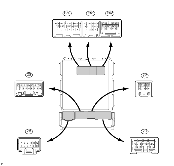
Disconnect the E50, E51, E52, 2E and 2C ECU connectors.
Measure the voltage and resistance of the wire harness side connector.
If the result is not as specified, there may be a malfunction on the wire harness side.Tester Connection Wiring Color Terminal Description Condition Specified Condition E51-1 (AM1) - Body ground Y - Body ground +B power supply Always 11 to 14 V E50-6 (AM2) - Body ground W - Body ground +B power supply Always 11 to 14 V E51-9 (SSW2) - Body ground B - Body ground Engine switch signal Engine switch pushed Below 1 Ω E51-9 (SSW2) - Body ground B - Body ground Engine switch signal Engine switch not pushed 10 kΩ or higher E51-10 (SSW1) - Body ground W - Body ground Engine switch signal Engine switch pushed Below 1 Ω E51-10 (SSW1) - Body ground W - Body ground Engine switch signal Engine switch not pushed 10 kΩ or higher E51-4 (GND2) - Body ground W-B - Body ground Ground Always Below 1 Ω E52-15 (CANH) - Body ground R - Body ground CAN Line Always 10 kΩ or higher E52-16 (CANL) - Body ground W - Body ground CAN Line Always 10 kΩ or higher E51-12 (CANN) - Body ground W - Body ground CAN Line Always 10 kΩ or higher E51-11 (CANP) - Body ground R - Body ground CAN Line Always 10 kΩ or higher 2E-17 (GND1) - Body ground W-B - Body ground Ground Always Below 1 Ω 2C-12 (LIN1) - Body ground V - Body ground LIN line Always 10 kΩ or higher Reconnect the ECU connectors.
Measure the voltage of the connector.
Tester Connection Wiring Color Terminal Description Condition Specified Condition E52-11 (ACCR) - E51-4 (GND2) P - W-B Starter assist signal
(ACC cut signal)Clutch pedal depressed, engine switch is pushed once → on (IG) 0.1 to 0.8 V *1
→ Output voltage at terminal AM1 or AM2 is -2 V or more.E51-5 (IG2D) - E51-4 (GND2) GR - W-B IG2 signal Engine switch on (IG) Output voltage at terminal AM1 or AM2 is -2 V or more. E51-5 (IG2D) - E51-4 (GND2) GR - W-B IG2 signal Engine switch on (ACC) Below 1 V E51-6 (IG1D) - E51-4 (GND2) W - W-B IG1 signal Engine switch on (IG) Output voltage at terminal AM1 or AM2 is -2 V or more. E51-6 (IG1D) - E51-4 (GND2) W - W-B IG1 signal Engine switch on (ACC) Below 1 V E52-3 (STR) - E51-4 (GND2) BR - W-B Clutch pedal switch signal Engine switch on (IG) Below 2 V → Pulse generation *3 E52-8 (INDW) - E51-4 (GND2) Y - W-B Warning signal Engine switch on (ACC, IG) Output voltage at terminal AM1 or AM2 is -3 V or more. E52-1 (INDS) - E51-4 (GND2) R - W-B Vehicle condition signal Clutch pedal depressed Output voltage at terminal AM1 or AM2 is -3 V or more. E50-18 (SLP) - E51-4 (GND2) G - W-B Steering lock actuator position signal Steering lock is locked Pulse generation
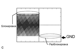
(See waveform 3)E50-18 (SLP) - E51-4 (GND2) G - W-B Steering lock actuator position signal Steering lock is released Pulse generation
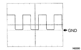
(See waveform 3)E50-7 (SLR+) - E51-4 (GND2) P - W-B Steering lock motor signal Steering lock motor operating Below 1 V E50-7 (SLR+) - E51-4 (GND2) P - W-B Steering lock motor signal Steering lock motor does not operate Output voltage at terminal AM1 or AM2 is -2 V or more. E50-4 (ACCD) - E51-4 (GND2) GR - W-B ACC signal Engine switch on (ACC) Output voltage at terminal AM1 or AM2 is -2 V or more. E50-4 (ACCD) - E51-4 (GND2) GR - W-B ACC signal Engine switch off Below 1 V E51-8 (SWIL) - E51-4 (GND2) G - W-B Illumination signal Light control switch TAIL or HEAD Output voltage at terminal AM1 or AM2 is -2 V or more. E52-2 (TACH) - E51-4 (GND2) GR - W-B Tachometer signal Engine running Pulse generation
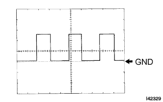
(See waveform 2)2C-8 (SPD) - E51-4 (GND2) V - W-B Vehicle speed signal Engine switch on (IG), rotate rear wheel slowly Pulse generation
(See waveform 1)E52-4 (STSW) - E51-4 (GND2) W - W-B Starter activation request signal Clutch pedal depressed, engine switch held on (ST) Output voltage at terminal AM1 or AM2 is -2 V or more. E52-14 (STR2) - E51-4 (GND2) W - W-B Starter signal (Sub) Clutch pedal depressed, engine switch on (ST) Output voltage at terminal AM1 or AM2 is -3.5 V or more. *2 2F-5 (ACC) - Body ground W - Body ground ACC power supply Always 11 to 14 V 2S-7 (IG) - Body ground L - Body ground IG power supply Always 11 to 14 V - УКАЗАНИЕ:
- *1: Voltage is output only when the engine is cranking.
- *2: Voltage is output for 0.3 seconds when the engine is cranking to start. Disconnect the B31 connector from the ECM and starter cut relay before measuring the voltage.
- *3: Remove the starter cut relay before measuring the voltage.
Using an oscilloscope, check the signal waveform of the ECU.
Waveform 1
Waveform 1 (Reference): Terminal No. 2C-8 (SPD) - E51-4 (GND2) Tool Setting 5 V/DIV., 10 ms./DIV. Vehicle Condition Driving at approx. 20 km/h (12 mph) - УКАЗАНИЕ:
- As the vehicle speed increases, the wavelength shortens.
Waveform 2
Waveform 2 (Reference): Terminal No. E52-2 (TACH) - E51-4 (GND2) Tool Setting 5 V/DIV., 10 ms./DIV. Vehicle Condition Engine idling - УКАЗАНИЕ:
- As the engine revolution speed increases, the wavelength shortens.
Waveform 3
Waveform 3 (Reference): Terminal No. E50-18 (SLP) - E51-4 (GND2) Tool Setting 2 V/DIV., 100 ms./DIV. Vehicle Condition Steering lock/unlock
| CHECK CERTIFICATION ECU |

Disconnect the E36 ECU connector.
Measure the voltage and resistance of the wire harness side connector.
If the result is not as specified, there may be a malfunction on the wire harness side.Tester Connection Wiring Color Terminal Description Condition Specified Condition E36-1 (+B) - Body ground W - Body ground +B power supply Always 11 to 14 V E36-10 (LIN) - Body ground V - Body ground LIN line Always 10 kΩ or higher E36-17 (E) - Body ground W-B - Body ground Ground Always Below 1 Ω Reconnect the ECU connector.
Measure the voltage of the connector.
If the result is not as specified, the ECU may have a malfunction.Tester Connection Wiring Color Terminal Description Condition Specified Condition E36-18 (IG) - Body ground B - Body ground Ignition power supply Engine switch on (IG) 11 to 14 V E36-18 (IG) - Body ground B - Body ground Ignition power supply Engine switch off Below 1 V
| CHECK ECM |
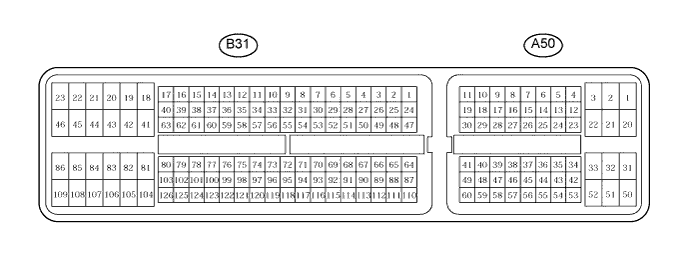
Disconnect the B31 and A50 ECM connectors.
Measure the voltage and resistance of the wire harness side connectors.
If the result is not as specified, there may be a malfunction on the wire harness side.Tester Connection Wiring Color Terminal Description Condition Specified Condition A50-1 (+B) - Body ground B - Body ground Power source of ECM Engine switch on (IG) 11 to 14 V A50-2 (BATT) - Body ground W - Body ground Power source of ECM Engine switch on (IG) 11 to 14 V A50-25 (IGSW) - Body ground B - Body ground Engine switch signal Engine switch on (IG) 11 to 14 V B31-44 (E02) - Body ground W-B - Body ground Ground Always Below 1 Ω B31-45 (E01) - Body ground BR - Body ground Ground Always Below 1 Ω B31-46 (E05) - Body ground W - Body ground Ground Always Below 1 Ω B31-109 (E1) - Body ground W - Body ground Ground Always Below 1 Ω Reconnect the ECM connectors.
Measure the voltage of the connectors.
Tester Connection Wiring Color Terminal Description Condition Specified Condition A50-24 (ACCR) - B31-109 (E1) L-Y - W ACC relay cut signal (output) Clutch pedal depressed, engine switch is pushed once → on (IG) 0.1 to 0.8 V *1 → Output voltage at terminal AM1 or AM2 is -2 V or more. A50-9 (STSW) - B31-109 (E1) W-G - W Starter activation request signal Clutch pedal depressed, engine switch held (on) Output voltage at terminal AM1 or AM2 is -2 V or more. A50-13 (TACH) - B31-109 (E1) GR - W Engine revolution signal (output) Idling Pulse generation (see waveform 1) A50-43 (STA) - B31-109 (E1) LG - W Starter relay operation signal Cranking 11 to 14 V B31-53 (STAR) - B31-109 (E1) W - W Starter signal (Main) Clutch pedal depressed, engine switch on (ST) 11 to 14 V - УКАЗАНИЕ:
- *1: Voltage is output only when the engine is cranking.
Using an oscilloscope, check the signal waveform of the ECM.
Waveform 1 (Reference): Terminal No. A50-13 (TACH) - B31-109 (E1) Tool Setting 5 V/DIV., 10 ms./DIV. Vehicle Condition Engine idling - УКАЗАНИЕ:
- As the vehicle speed increases, the wavelength shortens.
|
| CHECK STEERING LOCK ECU |
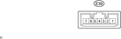
Disconnect the E39 ECU connector.
Measure the voltage and resistance of the wire harness side connector.
Tester Connection Wiring Color Terminal Description Condition Specified Condition E39-1 (GND) - Body ground W-B - Body ground Ground Always Below 1 Ω E39-2 (SGND) - Body ground BR - Body ground Ground Always Below 1 Ω E39-6 (IG2) - Body ground B - Body ground Ignition power supply Engine switch on (IG) 11 to 14 V E39-6 (IG2) - Body ground B - Body ground Ignition power supply Engine switch off Below 1 V E39-7 (B) - Body ground L - Body ground +B power supply Always 11 to 14 V - If the result is not as specified, there may be a malfunction on the wire harness side.
- If the result is not as specified, there may be a malfunction on the wire harness side.
Reconnect the E39 ECU connector.
Measure the voltage of the connector.
Tester Connection Wiring Color Terminal Description Condition Specified Condition E39-4 (SLP1) - E39-1 (GND) G - W-B Steering lock actuator position signal Steering is locked 11 to 14 V E39-4 (SLP1) - E39-1 (GND) G - W-B Steering lock actuator position signal Steering is released Below 1 V - If the result is not as specified, the ECU may have a malfunction.
- If the result is not as specified, the ECU may have a malfunction.