Dtc B2284 Brake Signal Malfunction. Corolla Auris
Двигатель. COROLLA, AURIS. ZZE150 ZRE151,152 NDE150
DESCRIPTION
WIRING DIAGRAM
INSPECTION PROCEDURE
READ VALUE OF INTELLIGENT TESTER (STOP LIGHT SWITCH)
CHECK DTC OUTPUT (CAN COMMUNICATION SYSTEM)
CHECK DTC OUTPUT (ENGINE CONTROL SYSTEM)
INSPECT FUSE (STOP)
CHECK HARNESS AND CONNECTOR (STOP FUSE - STOP LIGHT SWITCH)
INSPECT STOP LIGHT SWITCH
CHECK HARNESS AND CONNECTOR (STOP LIGHT SWITCH - MAIN BODY ECU)
DTC B2284 Brake Signal Malfunction |
DESCRIPTION
- УКАЗАНИЕ:
- When the main body ECU is replaced with a new one and the negative (-) battery terminal is connected, the power source mode becomes the IG-ON mode. When the battery is removed and reinstalled, the power source mode that was selected when the battery was removed is restored.
- After the main body ECU is replaced, perform the registration procedures for the engine immobiliser system.
DTC No.
| DTC Detection Condition
| Trouble Area
|
B2284
| The brake signal circuit between the main body ECU and the stop light switch is malfunctioning and the CAN information is inconsistent
| - Stop light switch
- CAN communication system
- ECM
- Main body ECU
- Wire harness or connector
|
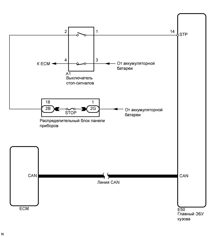
WIRING DIAGRAM
INSPECTION PROCEDURE
| EMERGENCY ENGINE START CONTROL |
If there is a malfunction in the stop light switch or STOP fuse, their signals may not be correctly transmitted to the main body ECU. This may result in the engine not starting even if the engine switch is pressed while the brake pedal is depressed and the shift lever is in the P position.
To activate the starter:
Turn the engine switch from off to on (ACC).
Press and hold the engine switch for 15 seconds.
- УКАЗАНИЕ:
- Before performing the inspection, depress the brake pedal and check that the stop lights come on. If the stop lights do not come on when the brake pedal is depressed, refer to the page shown in the brackets (See page Нажмите здесь).
| 1.READ VALUE OF INTELLIGENT TESTER (STOP LIGHT SWITCH) |
Connect the intelligent tester to the DLC3.
Turn the engine switch on (IG).
Check the DATA LIST for proper functioning of the stop light switch.
Body:Tester Display
| Measurement Item/Range
| Normal Condition
| Diagnostic Note
|
Stop Light SW
| Stop light switch/ON or OFF
| ON: Brake pedal depressed
OFF: Brake pedal released
| -
|
- OK:
- ON (brake pedal depressed) and OFF (brake pedal released) appear on the screen.
| 2.CHECK DTC OUTPUT (CAN COMMUNICATION SYSTEM) |
Delete the DTCs (See page Нажмите здесь).
Check for CAN communication system DTCs (See page Нажмите здесь).
- УКАЗАНИЕ:
- If the DTCs for the CAN communication system malfunction are output, inspect those DTCs first (See page Нажмите здесь).
- OK:
- No DTC is output.
| 3.CHECK DTC OUTPUT (ENGINE CONTROL SYSTEM) |
Delete the DTCs (See page Нажмите здесь).
Check for DTC P0500 (Vehicle speed sensor A).
- OK:
- No DTC is output.
| OK |
|
|
|
| REPLACE MAIN BODY ECU (INSTRUMENT PANEL JUNCTION BLOCK) |
|
Remove the STOP fuse from the instrument panel junction block.
Measure the resistance of the fuse.
- Standard resistance:
- Below 1 Ω
| 5.CHECK HARNESS AND CONNECTOR (STOP FUSE - STOP LIGHT SWITCH) |
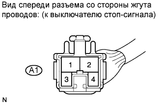
Disconnect the A1 switch connector.
Measure the voltage according to the value(s) in the table below.
- Standard voltage:
Tester Connection
| Condition
| Specified Condition
|
A1-2 - Body ground
| Always
| 11 to 14 V
|
| | REPAIR OR REPLACE HARNESS OR CONNECTOR |
|
|
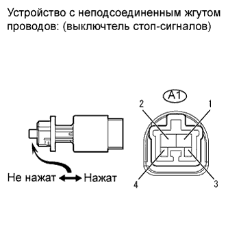
| 6.INSPECT STOP LIGHT SWITCH |
Remove the stop light switch (See page Нажмите здесь).
Measure the resistance according to the value(s) in the table below.
- Standard resistance:
Tester Connection
| Switch Condition
| Specified Condition
|
1 - 2
| Switch pin free
| Below 1 Ω
|
3 - 4
| Switch pin free
| 10 kΩ or higher
|
1 - 2
| Switch pin pushed in
| 10 kΩ or higher
|
3 - 4
| Switch pin pushed in
| Below 1 Ω
|
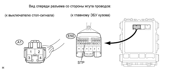
| 7.CHECK HARNESS AND CONNECTOR (STOP LIGHT SWITCH - MAIN BODY ECU) |
Disconnect E50 ECU connector.
Measure the resistance according to the value(s) in the table below.
- Standard resistance:
Tester Connection
| Condition
| Specified Condition
|
A1-1 - E50-14 (STP)
| Always
| Below 1 Ω
|
A1-2 - Body ground
| 10 kΩ or higher
|
| | REPAIR OR REPLACE HARNESS OR CONNECTOR |
|
|
| OK |
|
|
|
| REPLACE MAIN BODY ECU (INSTRUMENT PANEL JUNCTION BLOCK) |
|