Dtc B2282 Vehicle Speed Signal Malfunction. Corolla Auris
Двигатель. COROLLA, AURIS. ZZE150 ZRE151,152 NDE150
DESCRIPTION
WIRING DIAGRAM
INSPECTION PROCEDURE
CHECK CAN COMMUNICATION SYSTEM
CHECK COMBINATION METER SYSTEM
CHECK HARNESS AND CONNECTOR (COMBINATION METER - MAIN BODY ECU)
CHECK HARNESS AND CONNECTOR (MAIN BODY ECU - NO. 4 JUNCTION BLOCK)
DTC B2282 Vehicle Speed Signal Malfunction |
DTC B2283 Vehicle Speed Sensor Malfunction |
DESCRIPTION
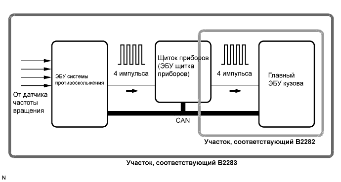
The skid control ECU converts these signals into 4-pulse signals and sends them to the combination meter. After this signal is converted into a more precise rectangular waveform by the waveform shaping circuit inside the combination meter, it is then transmitted to the main body ECU. The main body ECU determines the vehicle speed based on the frequency of these pulse signals.The main body ECU and the combination meter are connected by a cable and the CAN. DTC B2282 is output when the cable information and CAN information are inconsistent.- УКАЗАНИЕ:
- When the main body ECU is replaced with a new one and the negative (-) battery terminal is connected, the power source mode becomes the IG-ON mode. When the battery is removed and reinstalled, the power source mode that was selected when the battery was removed is restored.
- After the main body ECU is replaced, perform the registration procedures for the engine immobiliser system.
DTC No.
| DTC Detection Condition
| Trouble Area
|
B2282
| Cable information and CAN information between the main body ECU and the combination meter are inconsistent
| - CAN communication system
- Combination meter system
- Main body ECU
- Wire harness or connector
|
B2283
| When either of conditions below is met:
- Over-deceleration in vehicle speed
- Vehicle speed and engine speed do not match
| - DTC B2282 detection area
- Combination meter
- Speed sensor
- Main body ECU
- Wire harness or connector
|
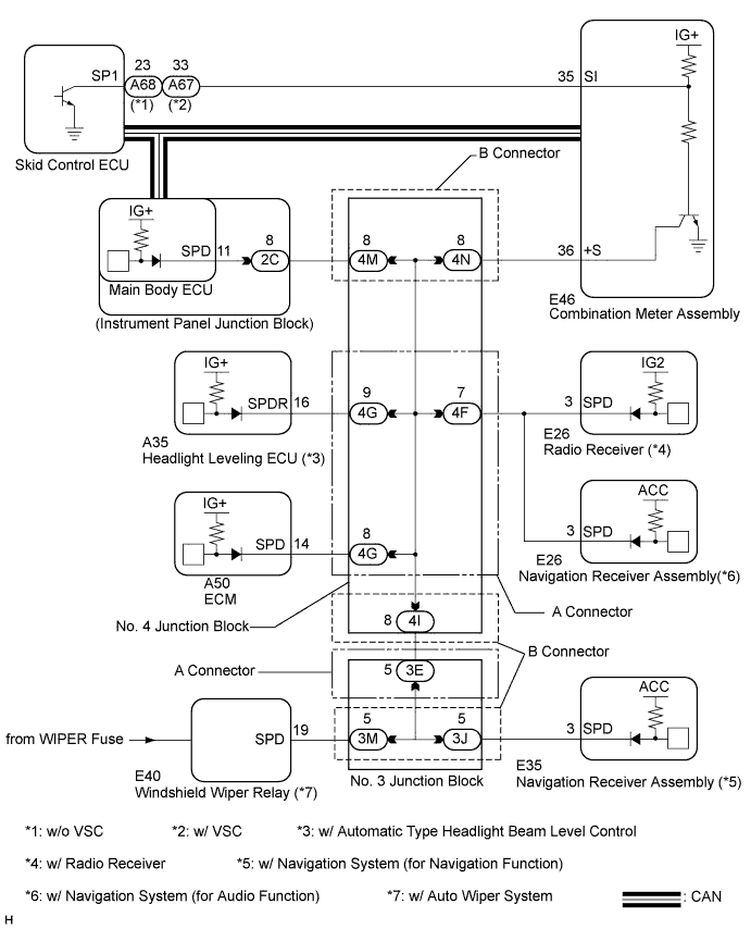
WIRING DIAGRAM
- УКАЗАНИЕ:
- A voltage of 12 V or 5 V is output from each ECU and then input to the combination meter. The signal is changed to a pulse signal at the transistor in the combination meter. Each ECU controls the respective system based on the pulse signal.
- If a short occurs in an ECU, all systems in the diagram above will not operate normally.
INSPECTION PROCEDURE
| 1.CHECK CAN COMMUNICATION SYSTEM |
Check for CAN communication system DTCs (See page Нажмите здесь).
- УКАЗАНИЕ:
- If the DTCs for the CAN communication system malfunction are output, inspect those DTCs first.
- Result:
Result
| Proceed to
|
CAN communication DTC is not output
| A
|
CAN communication DTC is output
| B
|
| 2.CHECK COMBINATION METER SYSTEM |
The circuits that send vehicle speed signals to this system are inspected in the meter system (See page Нажмите здесь).
During inspection for the meter section, if there is an instruction that indicates to go back to inspections for each system, proceed to the next step.
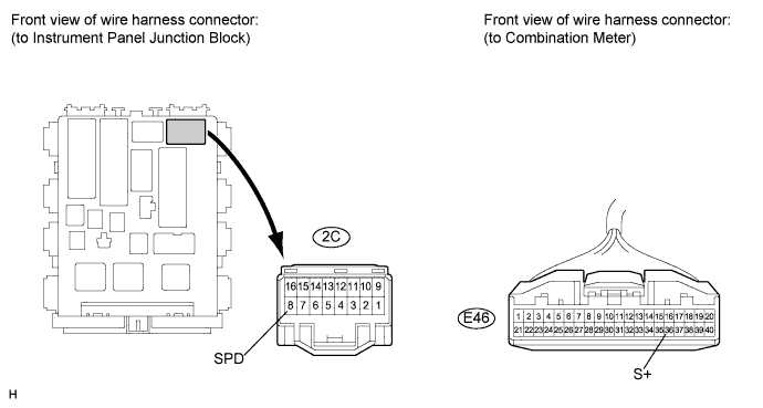
| 3.CHECK HARNESS AND CONNECTOR (COMBINATION METER - MAIN BODY ECU) |
Disconnect the E46 combination meter connector.
Disconnect the 2C junction block connector.
Measure the resistance according to the value(s) in the table below.
- Standard resistance:
Tester Connection
| Condition
| Specified Condition
|
2C-8 (SPD) - E46-36 (+S)
| Always
| Below 1 Ω
|
| OK |
|
|
|
| REPLACE MAIN BODY ECU (INSTRUMENT PANEL JUNCTION BLOCK) |
|
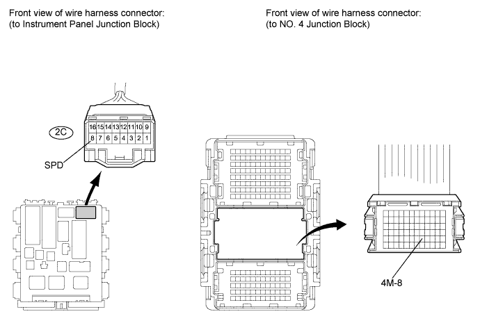
| 4.CHECK HARNESS AND CONNECTOR (MAIN BODY ECU - NO. 4 JUNCTION BLOCK) |
Disconnect the 2C connector.
Measure the resistance according to the value(s) in the table below.
- Standard resistance:
Tester Connection
| Condition
| Specified Condition
|
2C-8 (SPD) - 4M-8
| Always
| Below 1 Ω
|
| | REPAIR OR REPLACE HARNESS OR CONNECTOR (MAIN BODY ECU - NO. 4 JUNCTION BLOCK) |
|
|
| OK |
|
|
|
| REPLACE NO. 4 JUNCTION BLOCK |
|