Двигатель. COROLLA, AURIS. ZZE150 ZRE151,152 NDE150
WIRING DIAGRAM
DESCRIPTION
INSPECTION PROCEDURE
CHECK SOUND AREA
CHECK HARNESS AND CONNECTOR IN ENGINE COMPARTMENT
PERFORM CONFIRMATION DRIVING PATTERN
CHECK DTC OUTPUT (RELATING TO ENGINE)
PERFORM ACTIVE TEST BY INTELLIGENT TESTER (TEST THE FUEL LEAK)
READ VALUE OF DIESEL TURBO PRESSURE SENSOR, MASS AIR FLOW METER, AND FUEL PRESSURE SENSOR
READ VALUE OF INJECTOR ASSEMBLY (INJECTION FEEDBACK VAL AND INJECTION VOLUME)
CHECK INJECTOR COMPENSATION CODE
RESET ECM
CHECK INTAKE SYSTEM
CHECK EGR VALVE ASSEMBLY
INSPECT DIESEL THROTTLE BODY ASSEMBLY
CHECK COMBUSTION SOUND
PERFORM ACTIVE TEST BY INTELLIGENT TESTER (FUEL CUT FOR IDENTIFYING MALFUNCTION)
CHECK CYLINDER COMPRESSION PRESSURE
CHECK MALFUNCTIONING CYLINDER'S INJECTOR FOR DEPOSITS
CLEAN INJECTOR
READ VALUE OF INJECTOR ASSEMBLY (INJECTION FEEDBACK VAL AND INJECTION VOLUME)
IDENTIFY MALFUNCTIONING CYLINDER INJECTOR
PERFORM ACTIVE TEST BY INTELLIGENT TESTER (FUEL CUT FOR IDENTIFYING MALFUNCTIONING CYLINDER)
CHECK INJECTORS FOR DEPOSITS (EXCEPT FUEL ADDITION INJECTOR)
CLEAN INJECTOR
READ VALUE OF INJECTOR (INJECTION FEEDBACK VAL AND INJECTION VOLUME)
BLEED AIR FROM FUEL SYSTEM
CONFIRM WHETHER MALFUNCTION HAS BEEN SUCCESSFULLY REPAIRED
INSPECT COMMON RAIL ASSEMBLY (FUEL PRESSURE SENSOR)
INSPECT SUPPLY PUMP ASSEMBLY
СИСТЕМА ECD - Детонация или шум в двигателе |
WIRING DIAGRAM
Refer to DTC P0087 (See page Нажмите здесь) and DTC P0088 (See page Нажмите здесь).
DESCRIPTION
Malfunction Condition
| Main Trouble Area
| Related Trouble Area
|
- Knocking and abnormal sound due to extremely rich combustion
- Abnormal sound due to friction between parts
| - Injector malfunctions
- Injector sliding malfunction
- Injector stuck closed
- Injector stuck open
- Deposits in injector
- Injector circuit malfunction
- Abnormal common rail pressure
- Supply pump
- Fuel pulsation sound
- Air in fuel
- Friction between parts
- Compression pressure
| - Injector compensation codes
- Fuel leakage
- Intake air system leakage
- Intake air system blockage
- EGR system
- Throttle valve system
- Fuel pressure sensor
- Diesel turbo pressure sensor
- Atmosphere air pressure sensor (built into ECM)
- Vehicle modifications
- Low quality fuel
- Lack of fuel
- ECM
|
- УКАЗАНИЕ:
- Specified values in the following troubleshooting flowchart are for reference only. Variations in the Data List values may occur depending on the measuring conditions or the vehicle's age. Do not judge the vehicle to be normal even when the Data List values indicate a standard level. There are possibly some concealed factors of the malfunction.
- Check that the vehicle has not been modified in any way prior to the vehicle inspection.
INSPECTION PROCEDURE
- ПРИМЕЧАНИЕ:
- After replacing the supply pump, the ECM needs initialization (See page Нажмите здесь).
- After replacing an injector, the ECM needs registration (See page Нажмите здесь).
- УКАЗАНИЕ:
- This troubleshooting procedure checks for knocking and rattling.
- Knocking is most likely to occur while the engine is idling.
Find the source of the abnormal sound using a mechanic's stethoscope.
- Result:
Result
| Proceed to
|
Sound from supply pump
| A
|
Sound from parts other than supply pump
| B
|
| | REPAIR OR REPLACE MALFUNCTION PARTS |
|
|
| 2.CHECK HARNESS AND CONNECTOR IN ENGINE COMPARTMENT |
Check the wire harness connections.
- OK:
- The wire harnesses are connected securely.
| | REPAIR OR REPLACE HARNESS OR CONNECTOR |
|
|
| 3.PERFORM CONFIRMATION DRIVING PATTERN |
- УКАЗАНИЕ:
- Drive the vehicle according to the driving pattern below to allow the ECM to set DTCs relating to malfunctions of the fuel system, EGR system and throttle valve. If DTCs are set, problem areas can be identified.
Connect the intelligent tester to the DLC3.
Turn the ignition switch on (IG) and turn the tester on.
Enter CHECK MODE (See page Нажмите здесь).
Fully warm up the engine.
Allow the engine to idle for 5 minutes or more.
Drive the vehicle at more than 40 km/h (25 mph) for 1 minute or more (procedure "A").
Decelerate and stop the vehicle (procedure "B").
Repeat procedure "A" and procedure "B" 4 times or more.
Stop the engine and wait for at least 10 seconds (procedure "C").
Repeat steps procedure "A" and procedure "C" described above to set DTCs relating to the EGR system and throttle valve.
Drive the vehicle at more than 70 km/h (43 mph) for at least 1 minute (to set DTCs relating to the supply pump).
| 4.CHECK DTC OUTPUT (RELATING TO ENGINE) |
Connect the intelligent tester to the DLC3.
Turn the ignition switch on (IG) and turn the tester on.
Enter the following menus: Powertrain / Engine and ECT / DTC.
Read pending DTCs.
- Result:
Result
| Proceed to
|
DTC is not output
| A
|
Engine related DTCs
| B
|
| 5.PERFORM ACTIVE TEST BY INTELLIGENT TESTER (TEST THE FUEL LEAK) |
- УКАЗАНИЕ:
- By performing this Active Test, the engine speed is maintained. As a result, a fuel leak check can be conducted while retaining the high common rail pressure.
Connect the intelligent tester to the DLC3.
Start the engine and turn the tester on.
Enter the following menus: Powertrain / Engine and ECT / Active Test / Test the Fuel Leak.
Visually check the supply pump, injector, and fuel line located between the supply pump and common rail for fuel leaks and fuel pressure leaks. Also, perform the same check on the fuel line between the common rail and the injector.
- УКАЗАНИЕ:
- There may be fuel leaks inside components, such as the supply pump.
- OK:
- No fuel leakage
| | REPAIR OR REPLACE FUEL LEAKAGE POINT |
|
|
| 6.READ VALUE OF DIESEL TURBO PRESSURE SENSOR, MASS AIR FLOW METER, AND FUEL PRESSURE SENSOR |
Connect the intelligent tester to the DLC3.
Start the engine, warm it up, and turn the tester on.
Enter the following menus: Powertrain / Engine and ECT / Data List.
Select the following menu items in order and read the values.
- MAP
- MAF
- Fuel Press
- Standard value:
Item
| Engine Speed *1
| Standard Range
| Description
|
MAP *2
| Ignition switch on (IG) (engine stopped)
| Same as atmospheric pressure
| Intake manifold internal pressure detected by diesel turbo pressure sensor
|
Idling
| 85 to 94 kPa (638 to 705 mmHg, 25.10 to 27.76 in.Hg)
|
3000 rpm (no engine load)
| 120 to 140 kPa (900 to 1050 mmHg, 35.44 to 41.34 in.Hg)
|
3000 rpm (driving with full throttle acceleration) *5
| 239 to 255 kPa (1793 to 1913 mmHg, 70.58 to 75.30 in.Hg)
|
MAF *2, *4
| Ignition switch on (IG) (engine stopped)
| Less than 0.55 g/sec.
| Intake air volume detected by mass air flow meter
|
Idling
| 2.5 to 5.52 g/sec.
|
3000 rpm (no engine load)
| 49 to 60 g/sec.
|
3000 rpm (driving with full throttle acceleration) *5
| 124 to 136 g/sec.
|
Fuel Press*3
| Idling
| 37 to 43 MPa
| Common rail internal fuel pressure
|
2000 rpm (no engine load)
| 50 to 56 MPa
|
3000 rpm (no engine load)
| 60 to 66 MPa
|
3000 rpm (driving with full throttle acceleration) *5
| 150 to 156 MPa
|
- Result:
Item
| Result
| Proceed to
|
MAP, MAF, and Fuel Press
| Standard range
| A
|
MAP and MAF
| Outside standard range
| B
|
Only MAP
| Outside standard range
| C
|
Only MAF
| Outside standard range
| D
|
Only Fuel Press
| Outside standard range
| E
|
- УКАЗАНИЕ:
- *1: The air conditioner switch and all accessory switches should be OFF with a fully warmed-up engine.
- *2: This value is indicated when the ambient temperature is 25°C (77°F), the atmospheric pressure is 101 kPa (758 mmHg, 29.83 in.Hg), and the stable boost pressure is maintained for approximately 10 seconds.
- *3: This value is indicated when the ambient temperature is 25°C (77°F), the atmospheric pressure is 101 kPa (758 mmHg, 29.83 in.Hg), and the vehicle is accelerated for approximately 10 seconds.
- *4: When the mass air flow meter malfunctions, the MAF output may deviate from the standard (referential) range when the engine idles and is accelerated from 3000 to 4000 rpm with full throttle acceleration.
- *5: Fully depress the accelerator pedal with the vehicle creeping at idle speed in 2nd gear.
| |
|
| | GO TO DTC PO105, P0107 AND P0108 (RELATED TO DIESEL TURBO PRESSURE SENSOR) |
|
|
| | GO TO DTC P0100, P0102 AND P0103 (RELATED TO MASS AIR FLOW METER) |
|
|
| |
|
| 7.READ VALUE OF INJECTOR ASSEMBLY (INJECTION FEEDBACK VAL AND INJECTION VOLUME) |
Connect the intelligent tester to the DLC3.
Start the engine, warm it up, and turn the tester on.
Select the following menu items in order and read the values.
- Injection Feedback Val #1, #2, #3, and #4
- Injection Volume
- Standard value:
Item
| Engine Speed*
| Standard Range
| Description
|
Injection Feedback Val #1
| Idling
| -3.5 to 3.5 mm3
| Value of injector fuel injection volume compensates for differences in combustion condition of cylinders
- Positive values indicate control which corrects combustion degradation
- Negative values indicate control which corrects excessive combustion pressure
- If problems exist, Injection Feedback Val may deviate from -3.5 and 3.5 mm3 range
|
Injection Feedback Val #2
| Idling
| -3.5 to 3.5 mm3
|
Injection Feedback Val #3
| Idling
| -3.5 to 3.5 mm3
|
Injection Feedback Val #4
| Idling
| -3.5 to 3.5 mm3
|
Injection Volume
| Idling
| 2.8 to 7.3 mm3
| Fuel injection volume value controlled by ECU
- Controls NE signal, fuel temperature, engine coolant temperature, intake air temperature, boost pressure, atmospheric pressure, and EGR volume
- If problems exist, Injection Volume may be outside standard range
|
- Result:
Result
| Proceed to
|
Standard range
| A
|
Injection Feedback Val #1 to #4 and/or Injection Volume outside standard range
| B
|
- УКАЗАНИЕ:
- *: The air conditioner switch and all accessory switches should be OFF, and the engine should be fully warmed up.
| 8.CHECK INJECTOR COMPENSATION CODE |
- УКАЗАНИЕ:
- If the injector compensation code is not correctly registered, it may cause malfunctions (See page Нажмите здесь).
- OK:
- Compensation code of the installed injector is the same as the code registered in the ECM.
| | REGISTER INJECTOR COMPENSATION CODE |
|
|
Disconnect the cable from the negative (-) battery terminal for at least 2 minutes.
Reconnect the cable to the negative (-) battery terminal.
Check whether the malfunction has been successfully repaired by performing a driving test using the freeze frame data recorded at the time the malfunction occurred.
- OK:
- Malfunction has been repaired successfully.
Check for air leakage and blockage between the air cleaner and turbocharger.
Check for air leakage and blockage between the turbocharger and intake manifold.
- OK:
- No air leakage or blockage
| 11.CHECK EGR VALVE ASSEMBLY |
Check the EGR valve assembly (See page Нажмите здесь).
| 12.INSPECT DIESEL THROTTLE BODY ASSEMBLY |
Connect the intelligent tester to the DLC3.
Turn the ignition switch on (IG) and turn the tester on.
Enter the following menus: Powertrain / Engine and ECT / Data List / Diesel Throttle Angle.
Read the value.
- Standard value:
- Ignition switch on (IG):
- 0%
- Idling (Warmed up engine):
- 95%
- Accelerator pedal fully depressed:
- 0%
| 13.CHECK COMBUSTION SOUND |
Confirm type of sound emitted.
- Result:
Result
| Proceed to
|
Knocking
| A
|
Mechanical sound other than knocking
| B
|
| 14.PERFORM ACTIVE TEST BY INTELLIGENT TESTER (FUEL CUT FOR IDENTIFYING MALFUNCTION) |
Connect the intelligent tester to the DLC3.
Start the engine and turn the tester on.
Enter the following menus: Powertrain / Engine and ECT / Active Test / Control the Cylinder #1, #2, #3, and #4 Fuel Cut.
Check the four cylinders in sequence to identify any faulty cylinders by performing the power balance inspection.
- УКАЗАНИЕ:
- While the engine is idling, if the idling stability variation is small despite cutting off the fuel injection, the cylinder is malfunctioning.
- With normal cylinders, the engine idles roughly when the fuel injection is cut off.
| 15.CHECK CYLINDER COMPRESSION PRESSURE |
Check the cylinder compression pressure (See page Нажмите здесь).
- Standard pressure:
- 2700 kPa (27.5 kgf/cm2, 392 psi)
- Minimum pressure:
- 2200 kPa (22.5 kgf/cm2, 320 psi)
- Difference between each cylinder:
- 500 kPa (5.0 kgf/cm2, 71 psi)
| | CHECK ENGINE TO DETERMINE CAUSE OF LOW COMPRESSION |
|
|
| 16.CHECK MALFUNCTIONING CYLINDER'S INJECTOR FOR DEPOSITS |
- УКАЗАНИЕ:
- If an injector is contaminated with the deposits, the fuel injection volume deviates from the standard range. This may cause malfunctions.
Check the injector for any deposits.
- Result:
Result
| Proceed to
|
Deposits
| A
|
No deposits
| B
|
| | REPLACE INJECTOR ASSEMBLY OF MALFUNCTIONING CYLINDER (Нажмите здесь) |
|
|
Wipe away the deposits from the tips of the injectors.
- УКАЗАНИЕ:
- Solvent or carbon removal agents help remove the deposits easily.
- Exercise extreme care not to damage the injectors while wiping off the deposits.
| 18.READ VALUE OF INJECTOR ASSEMBLY (INJECTION FEEDBACK VAL AND INJECTION VOLUME) |
Reinstall the injector to the cylinder head.
Connect the intelligent tester to the DLC3.
Turn the ignition switch on (IG) and turn the tester on.
Start the engine and warm it up.
Enter the following menus: Powertrain / Engine and ECT / Data List.
Select the following menu items in order and read the values.
- Injection Feedback Val #1, #2, #3, and #4
- Injection Volume
- Standard value:
Item
| Engine Speed*
| Reference Value
|
Injection Feedback Val #1 to #4
| Idling
| -3.5 to 3.5 mm3
|
Injection Volume
| Idling
| 2.8 to 7.3 mm3
|
- УКАЗАНИЕ:
- *: The air conditioner switch and all accessory switches should be OFF, and the engine should be fully warmed up.
- When the values are outside the standard range, deposits inside the injector may be causing the problem.
- OK:
- The values are within the standard range.
| | REPLACE INJECTOR ASSEMBLY OF MALFUNCTIONING CYLINDER (Нажмите здесь) |
|
|
| 19.IDENTIFY MALFUNCTIONING CYLINDER INJECTOR |
Follow the instructions in the table below according to the check result of the intelligent tester.
- УКАЗАНИЕ:
- This operation is based on the premise that the common rail pressure is normal.
- Standard value:
Item
| Engine Speed*
| Reference Value
|
Injection Feedback Val #1 to #4
| Idling
| -3.5 to 3.5 mm3
|
Injection Volume
| Idling
| 2.8 to 7.3 mm3
|
- УКАЗАНИЕ:
- *: The air conditioner switch and all accessory switches should be OFF, and the engine should be fully warmed up.
- Result:
Injection Volume
| Injection Volume
|
Injection Feedback Val #1 to #4
| Less than 2.8 mm3
| Between 2.8 and 7.3 mm3 (Normal)
| More than 7.3 mm3
|
3.5 mm3 or more, -3.5 mm3 or less
| A
| B
| B
|
Between -3.5 and 3.5 mm3
| -
| Normal
| C*
|
Proceed to
| Inspection Area
| Description
|
A
| Inspect and repair cylinder injector with revised injection volume of less than -3.5 mm3:
- Perform power balance inspection and identify malfunctioning cylinder
- Replace malfunctioning cylinder injector
| Abnormal value cylinder injector injects excessively large quantity of fuel
|
B
| Identify malfunctioning cylinders by conducting power balance inspection:
- Perform power balance inspection to identify malfunctioning cylinders
- Clean malfunctioning cylinder injector, then check and repair it
| Abnormal value cylinder injector injects excessively large quantity of fuel:
- Fuel injection volume too low due to injector nozzle being blocked by deposits
- Abnormal value cylinder injector compression decreases
- Abnormal value cylinder injector injects excessively large quantity of fuel
|
C
| Inspect and repair all cylinder injectors:
Clean all cylinder injectors, and then inspect and repair them
| All cylinder injectors inject excessively small quantity of fuel:
Fuel injection volume too low due to all cylinder injector nozzles being blocked by deposits
|
- УКАЗАНИЕ:
- *: When the Injection Volume displayed on the intelligent tester is large despite the Fuel Press and Injection Feedback Val #1 to #4 in the Data List being normal, the injector may be clogged. In this case, there may be deposits inside or outside the injector.
- Despite the injector functioning normally, the indicated Injection Feedback Val #1 to #4 values may be outside the normal operating range due to compensation for other problems (such as low compression).
- Injection Feedback Val #1 to #4 is the value used to correct the fuel injection volumes of each cylinder, in order to optimize (compensate for the unevenness between) all the cylinder combustion conditions. If any of the cylinders malfunction, the fuel injection volumes for the normal cylinders are corrected simultaneously. As a result, the Injection Feedback Val #1 to #4 may deviate from the standard range.
| 20.PERFORM ACTIVE TEST BY INTELLIGENT TESTER (FUEL CUT FOR IDENTIFYING MALFUNCTIONING CYLINDER) |
Connect the intelligent tester to the DLC3.
Start the engine and turn the tester on.
Enter the following menus: Powertrain / Engine and ECT / Active Test / Control the Cylinder #1, #2, #3, and #4 Fuel Cut.
Check the four cylinders in sequence to identify any faulty cylinders by performing the power balance inspection.
- УКАЗАНИЕ:
- If the engine idle does not change when an injector is disabled, the cylinder being tested is malfunctioning.
- If the cylinder being tested is normal, there will be a significant change of idle speed when the fuel injection is stopped for that cylinder.
| NEXT |
|
|
|
| REPLACE INJECTOR ASSEMBLY OF MALFUNCTIONING CYLINDER (Нажмите здесь) |
|
| 21.CHECK INJECTORS FOR DEPOSITS (EXCEPT FUEL ADDITION INJECTOR) |
- УКАЗАНИЕ:
- If an injector is contaminated with the deposits, the fuel injection volume deviates from the standard range. This may cause malfunctions.
Check the injector for any deposits.
- Result:
Result
| Proceed to
|
Injector condition: Deposits
| A
|
Injector condition: No deposits
| B
|
Wipe away the deposits from the tips of the injectors.
- УКАЗАНИЕ:
- Solvent or carbon removal agents help remove the deposits easily.
- Exercise extreme care not to damage the injectors while wiping off the deposits.
| 23.READ VALUE OF INJECTOR (INJECTION FEEDBACK VAL AND INJECTION VOLUME) |
Reinstall the injector to the cylinder head.
Connect the intelligent tester to the DLC3.
Turn the ignition switch on (IG) and turn the tester on.
Start the engine and warm it up.
Enter the following menus: Powertrain / Engine and ECT / Data List.
Select the following menu items in order and read the values displayed on the tester respectively.
- Injection Feedback Val #1, #2, #3, and #4
- Injection Volume
- Standard value:
Item
| Engine Speed*
| Reference Value
|
Injection Feedback Val #1 to #4
| Idling
| -3.5 to 3.5 mm3
|
Injection Volume
| Idling
| 2.8 to 7.3 mm3
|
- УКАЗАНИЕ:
- *: The air conditioner switch and all accessory switches should be OFF, and the engine should be fully warmed up.
- When the values are outside the standard range, deposits inside the injector may be causing the problem.
- OK:
- The values are within the standard range.
| 24.BLEED AIR FROM FUEL SYSTEM |
To bleed air from the priming pump, pump the priming pump until it becomes hard and cannot be pumped any more.
| 25.CONFIRM WHETHER MALFUNCTION HAS BEEN SUCCESSFULLY REPAIRED |
Check whether the knocking has been successfully repaired by performing a driving test.
- OK:
- Malfunction has been repaired successfully.
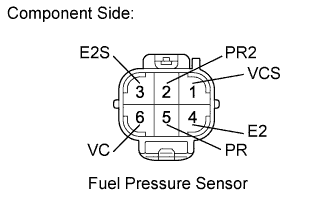
| 26.INSPECT COMMON RAIL ASSEMBLY (FUEL PRESSURE SENSOR) |
Disconnect the fuel pressure sensor connector.
Measure the resistance according to the value(s) in the table below.
- Standard resistance:
Tester Connection
| Condition
| Specified Condition
|
5 (PR) - 4 (E2)
| Always
| 16.4 kΩ or less
|
2 (PR2) - 3 (E2S)
| Always
| 16.4 kΩ or less
|
5 (PR) - 6 (VC)
| Always
| 3 kΩ or less
|
2 (PR2) - 1 (VCS)
| Always
| 3 kΩ or less
|
Reconnect the fuel pressure sensor connector.
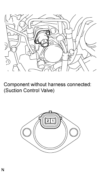
| 27.INSPECT SUPPLY PUMP ASSEMBLY |
Disconnect the suction control valve connector.
Measure the resistance according to the value(s) in the table below.
- Standard resistance:
Tester Connection
| Condition
| Specified Condition
|
1 - 2
| 20°C (68°F)
| 1.9 to 2.3 Ω
|
Reconnect the suction control valve connector.
| OK |
|
|
|
| REPAIR OR REPLACE COMMON RAIL ASSEMBLY (PRESSURE DISCHARGE VALVE) |
|