Система Ecd Цепь Предпускового Подогрева. Corolla Auris
Двигатель. COROLLA, AURIS. ZZE150 ZRE151,152 NDE150
DESCRIPTION
WIRING DIAGRAM
INSPECTION PROCEDURE
CHECK GLOW PLUG RELAY (VOLTAGE)
INSPECT GLOW PLUG RELAY (VOLTAGE)
INSPECT GLOW PLUG RELAY
CHECK HARNESS AND CONNECTOR (GLOW PLUG RELAY - GLOW PLUG)
INSPECT GLOW PLUG ASSEMBLY (RESISTANCE)
CHECK GLOW PLUG ASSEMBLY (INSTALLATION)
CHECK HARNESS AND CONNECTOR (GLOW PLUG RELAY - ECM)
INSPECT FUSE (GLOW FUSE)
INSPECT FUSE (EFI NO. 2 FUSE)
CHECK HARNESS AND CONNECTOR (GLOW PLUG RELAY - INTEGRATION RELAY (EFI MAIN RELAY))
СИСТЕМА ECD - Цепь предпускового подогрева |
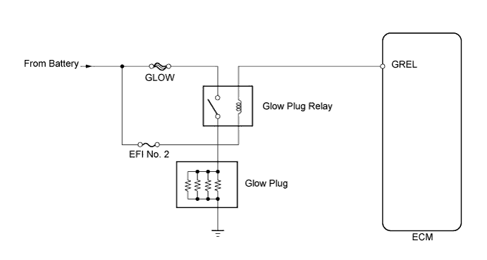
DESCRIPTION
The glow plug is mounted inside the engine combustion chamber. To ensure efficient engine starting with a cold engine, the ECM calculates a time interval that the current needs to flow through the glow plug depending on the starting engine coolant temperature when the ignition switch is turned to the ON position. The ECM then turns on the glow plug relay and permits the current to flow through the glow plug based on the ECM's calculated time. The glow plug relay is then heated, and enhances fuel combustion with a cold engine. - УКАЗАНИЕ:
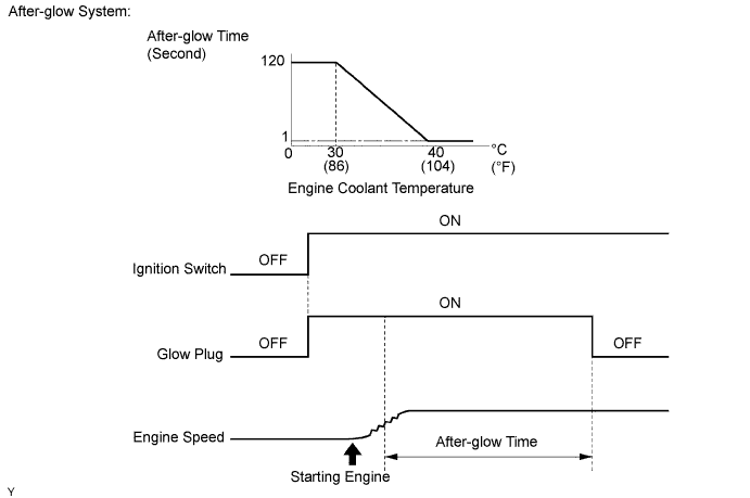
- These troubleshooting procedures are for: 1) difficulty starting engine in cold weather, and 2) difficulty driving/vehicle malfunctions in cold weather immediately after the engine is started.
- After the engine is started, the ECM performs an "after-glow" for a certain period of time. In proportion to the actual engine coolant temperature, the time period varies. The after-glow reduces diesel engine knocking, white smoke emissions and engine noise when the engine is cold.
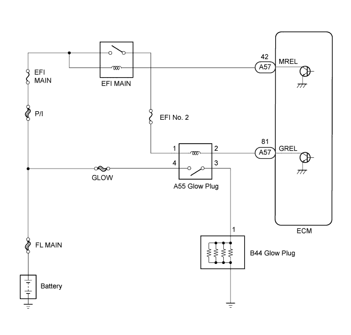
WIRING DIAGRAM
INSPECTION PROCEDURE
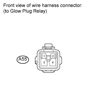
| 1.CHECK GLOW PLUG RELAY (VOLTAGE) |
Disconnect the glow plug relay connector.
Measure the voltage according to the value(s) in the table below.
- Standard voltage:
Tester Connection
| Condition
| Specified Condition
|
A55-4 - Body ground
| Always
| 9 to 14 V
|
Connect the glow plug relay connector.
| 2.INSPECT GLOW PLUG RELAY (VOLTAGE) |
Disconnect the glow plug relay connector.
Turn the ignition switch to the ON position.
Measure the voltage according to the value(s) in the table below.
- Standard voltage:
Tester Connection
| Switch Condition
| Specified Condition
|
A55-1 - Body ground
| Ignition switch ON
| 9 to 14 V
|
Turn the ignition switch off.
Reconnect the glow plug relay connector.
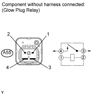
| 3.INSPECT GLOW PLUG RELAY |
Disconnect the glow plug relay connector.
Measure the resistance according to the value(s) in the table below.
- Standard resistance:
Tester Connection
| Condition
| Specified Condition
|
3 - 4
| When battery voltage not applied to terminals 1 and 2
| 10 kΩ or higher
|
3 - 4
| When battery voltage applied to terminals 1 and 2
| Below 1 Ω
|
Reconnect the glow plug relay.
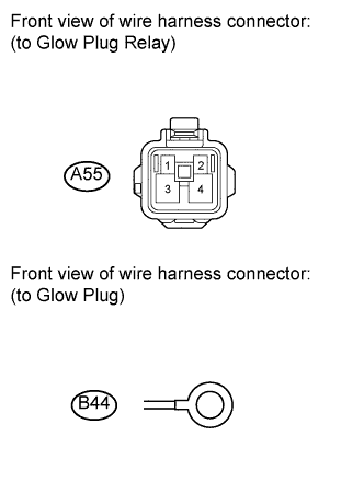
| 4.CHECK HARNESS AND CONNECTOR (GLOW PLUG RELAY - GLOW PLUG) |
Disconnect the glow plug relay connector.
Disconnect the glow plug connector.
Measure the resistance according to the value(s) in the table below.
- Standard resistance (check for open):
Tester Connection
| Condition
| Specified Condition
|
A55-3 - B44-1
| Always
| Below 1 Ω
|
- Standard resistance (check for short):
Tester Connection
| Condition
| Specified Condition
|
A55-3 or B44-1 - Body ground
| Always
| 10 kΩ or higher
|
Reconnect the glow plug relay connector.
Reconnect glow plug connector.
| | REPAIR OR REPLACE HARNESS OR CONNECTOR (GLOW PLUG RELAY - GLOW PLUG) |
|
|
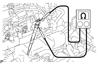
| 5.INSPECT GLOW PLUG ASSEMBLY (RESISTANCE) |
Remove the glow plug connector.
Measure the resistance according to the value(s) in the table below.
- Standard resistance:
Tester Connection
| Condition
| Specified Condition
|
Glow plug terminal - Body ground
| 20°C (68°F)
| 0.55 to 0.68 Ω
|
- УКАЗАНИЕ:
- If any of the glow plugs has an open malfunction, the engine power is insufficient only when the engine is cold.
- ПРИМЕЧАНИЕ:
- Exercise extreme care not to damage the glow plug pipes. Damaging them could cause an open circuit, or shorten the life of the glow plugs.
- Keep the glow plugs free of oil and fuel while cleaning.
- Wipe any oil off of the terminal and Bakelite washer with a clean, dry cloth during inspection.
- Do not apply more than 11 V to the glow plugs as it may cause an open circuit.
Reinstall the glow plug connector.
| 6.CHECK GLOW PLUG ASSEMBLY (INSTALLATION) |
Check the glow plug installation.
- OK:
- The glow plugs are installed securely.
- Torque:
- 13 N*m (127 kgf*cm, 9 ft.*lbf)
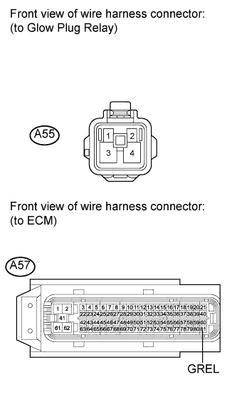
| 7.CHECK HARNESS AND CONNECTOR (GLOW PLUG RELAY - ECM) |
Disconnect the glow plug relay connector.
Disconnect the ECM connector.
Measure the resistance according to the value(s) in the table below.
- Standard resistance (check for open):
Tester Connection
| Condition
| Specified Condition
|
A55-2 - A57-81 (GREL)
| Always
| Below 1 Ω
|
- Standard resistance (check for short):
Tester Connection
| Condition
| Specified Condition
|
A55-2 or A57-81 (GREL) - Body ground
| Always
| 10 kΩ or higher
|
Reconnect the glow plug relay connector.
Reconnect the ECM connector.
| | REPAIR OR REPLACE HARNESS OR CONNECTOR (GLOW PLUG RELAY - ECM) |
|
|
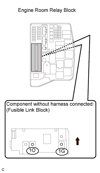
| 8.INSPECT FUSE (GLOW FUSE) |
Remove the fusible link block from the engine room relay block.
Measure the resistance according to the value(s) in the table below.
- Standard resistance:
Tester Connection
| Condition
| Specified Condition
|
1G-1 - 1O-1
| Always
| Below 1 Ω
|
Reinstall the glow fuse.
| OK |
|
|
|
| REPAIR OR REPLACE HARNESS OR CONNECTOR (GLOW RELAY - BATTERY) |
|
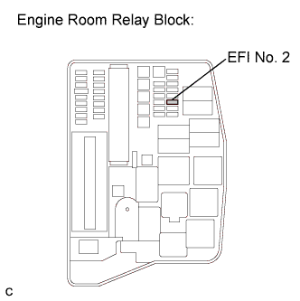
| 9.INSPECT FUSE (EFI NO. 2 FUSE) |
Remove the EFI No. 2 fuse from the engine room relay block.
Measure the resistance according to the value(s) in the table below.
- Standard resistance:
Tester Connection
| Condition
| Specified Condition
|
EFI No. 2 fuse
| Always
| Below 1 Ω
|
Reinstall the EFI No. 2 fuse.
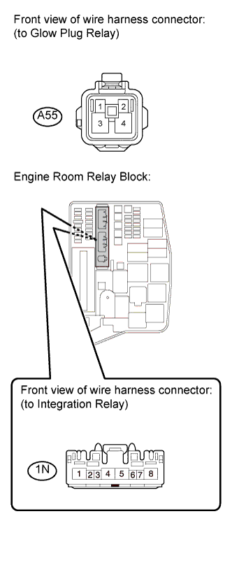
| 10.CHECK HARNESS AND CONNECTOR (GLOW PLUG RELAY - INTEGRATION RELAY (EFI MAIN RELAY)) |
Disconnect the glow plug relay connector.
Remove the integration relay from the engine room relay block.
Measure the resistance according to the value(s) in the table below.
- Standard resistance (check for open):
Tester Connection
| Condition
| Specified Condition
|
A55-1 - 1N-8
| Always
| Below 1 Ω
|
- Standard resistance (check for short):
Tester Connection
| Condition
| Specified Condition
|
A55-1 or 1N-8 - Body ground
| Always
| 10 kΩ or higher
|
Reconnect the glow plug relay connector.
Reinstall the integration relay.
| | REPAIR OR REPLACE HARNESS OR CONNECTOR (GLOW PLUG RELAY INTEGRATION RELAY (EFI MAIN RELAY)) |
|
|