Двигатель. COROLLA, AURIS. ZZE150 ZRE151,152 NDE150
WIRING DIAGRAM
INSPECTION PROCEDURE
CHECK DTC OUTPUT (RELATED TO ENGINE)
READ VALUE OF INJECTOR ASSEMBLY (INJECTION VOLUME AND INJECTION FEED BACK VAL #1 TO #4)
PERFORM ENGINE RPM ACCELERATION
CHECK AIR INTAKE SYSTEM AND EXHAUST SYSTEM
CHECK EGR VALVE ASSEMBLY
CHECK TURBOCHARGING PRESSURE
PERFORM ACTIVE TEST BY FUEL PRESSURE SENSOR AND INJECTOR ASSEMBLY
CHECK CYLINDER COMPRESSION PRESSURE
CHECK HARNESS AND CONNECTOR (INJECTOR - EDU)
PERFORM ACTIVE TEST BY INTELLIGENT TESTER (CONTROL THE CYLINDER FUEL CUT)
READ VALUE USING INTELLIGENT TESTER (ENGINE COOLANT TEMPERATURE)
READ VALUE OF DIESEL TURBO PRESSURE SENSOR
READ VALUE USING INTELLIGENT TESTER (ENGINE SPEED)
READ VALUE USING INTELLIGENT TESTER (ACCEL POSITION 1 AND 2)
READ VALUE USING INTELLIGENT TESTER (INTAKE AIR TEMPERATURE)
READ VALUE USING INTELLIGENT TESTER (FUEL PRESSURE)
INSPECT ENGINE COOLANT TEMPERATURE SENSOR
CHECK HARNESS AND CONNECTOR (DIESEL TURBO PRESSURE SENSOR - ECM)
INSPECT CRANKSHAFT POSITION SENSOR
CHECK HARNESS AND CONNECTOR (ACCELERATOR PEDAL POSITION SENSOR - ECM)
INSPECT DIESEL TURBO INTAKE AIR TEMPERATURE SENSOR
INSPECT COMMON RAIL ASSEMBLY (FUEL PRESSURE SENSOR)
CHECK HARNESS AND CONNECTOR (FUEL PRESSURE SENSOR - ECM)
REPLACE ECM
СИСТЕМА ECD - Черный дым на выпуске |
WIRING DIAGRAM
Refer to DTC P0087 (See page Нажмите здесь), DTC P0105 (See page Нажмите здесь), DTC P0200 (See page Нажмите здесь), P0335 (See page Нажмите здесь) and DTC P2120 (See page Нажмите здесь).
INSPECTION PROCEDURE
- ПРИМЕЧАНИЕ:
- After replacing the ECM, the new ECM needs registration (See page Нажмите здесь) and initialization (See page Нажмите здесь).
- After replacing a supply pump, the ECM needs initialization (See page Нажмите здесь).
- After replacing an injector, the ECM needs registration (See page Нажмите здесь).
- УКАЗАНИЕ:
- Specified values in the following troubleshooting flowchart are for reference only. Variations in the Data List values may occur depending on the measuring conditions or the vehicle's age. Do not assume the vehicle to be normal when the Data List outputs standard values. There may be concealed factors of the malfunction.
| 1.CHECK DTC OUTPUT (RELATED TO ENGINE) |
Connect the intelligent tester to the DLC3.
Turn the ignition switch on (IG) and turn the tester on.
Enter the following menus: Powertrain / Engine and ECT / DTC.
Read the DTCs.
- Result:
Result
| Proceed to
|
DTC is not output
| A
|
DTCs related to the engine
| B
|
| | REPAIR OR REPLACE ENGINE CONTROL SYSTEM ACCORDING TO DTC OUTPUT |
|
|
| 2.READ VALUE OF INJECTOR ASSEMBLY (INJECTION VOLUME AND INJECTION FEED BACK VAL #1 TO #4) |
Connect the intelligent tester to the DLC3.
Start the engine and turn the tester on.
Enter the following menus: Powertrain / Engine and ECT / Data List.
Select the following menu items in order and read the values.
- Injection Volume
- Injection Feedback Val #1, #2, #3, and #4
- Standard value:
Item
| Engine Speed*
| Reference Value
|
Injection Volume
| Idling (No engine load)
| 3.2 to 10.1 mm3
|
Injection Feedback Val #1
| Idling (No engine load)
| -3.5 to 3.5 mm3
|
Injection Feedback Val #2
| Idling (No engine load)
| -3.5 to 3.5 mm3
|
Injection Feedback Val #3
| Idling (No engine load)
| -3.5 to 3.5 mm3
|
Injection Feedback Val #4
| Idling (No engine load)
| -3.5 to 3.5 mm3
|
- УКАЗАНИЕ:
- *: If no idling conditions are specified, the shift lever should be in the neutral position, and the air conditioner switch and all accessory switches should be OFF.
| 3.PERFORM ENGINE RPM ACCELERATION |
- УКАЗАНИЕ:
- If the exhaust gas contains excessive black smoke, perform the following operations:
Accelerate the engine speed to the maximum rpm with no load 20 times.
Check the volume of black smoke in the exhaust gas.
- Result:
Result
| Proceed to
|
Black smoke is not present
| OK
|
Black smoke remains in the exhaust gas
| NG
|
- УКАЗАНИЕ:
- Soot deposits in the exhaust system may cause excessive black smoke.
| 4.CHECK AIR INTAKE SYSTEM AND EXHAUST SYSTEM |
Inspect the engine condition (See page Нажмите здесь).
| | CHECK AND REPLACE LOCATIONS WHERE MALFUNCTIONS EXIST |
|
|
| 5.CHECK EGR VALVE ASSEMBLY |
Check the EGR valve assembly (See page Нажмите здесь).
| 6.CHECK TURBOCHARGING PRESSURE |
Check the turbocharger pressure (See page Нажмите здесь).
- Standard pressure:
- 58.5 to 78.9 kPa (0.60 to 0.80 kgf/cm2, 8.5 to 11.4 psi)
| 7.PERFORM ACTIVE TEST BY FUEL PRESSURE SENSOR AND INJECTOR ASSEMBLY |
Connect the intelligent tester to the DLC3.
Start the engine and turn the tester on.
Enter the following menus: Powertrain / Engine and ECT / Data List.
Select the following menu items in order and read the values.
- Fuel Press
- Injection Volume
- Main Injection
- Pilot 2 Injection
- Injection Feedback Val #1, #2, #3, and #4
- Reference:
Item
| Engine Speed*
| Reference Value
|
Fuel Press
| Idling
| 35 to 45 MPa
|
Fuel Press
| 2000 rpm (no engine load)
| 51 to 61 MPa
|
Fuel Press
| 3000 rpm (no engine load)
| 57 to 68 MPa
|
Injection Volume
| Idling
| 3.2 to 10.1 mm3
|
Injection Volume
| 2000 rpm (no engine load)
| 3.2 to 8.7 mm3
|
Injection Volume
| 3000 rpm (no engine load)
| 5.7 to 10.7 mm3
|
Main Injection
| Idling
| 374 to 588 μs
|
Pilot 1 Injection
| Idling
| 319 to 433 μs
|
Pilot 2 Injection
| Idling
| 319 to 433 μs
|
Injection Feedback Val #1
| Idling
| -3.5 to 3.5 mm3
|
Injection Feedback Val #2
| Idling
| -3.5 to 3.5 mm3
|
Injection Feedback Val #3
| Idling
| -3.5 to 3.5 mm3
|
Injection Feedback Val #4
| Idling
| -3.5 to 3.5 mm3
|
- УКАЗАНИЕ:
- If no idling conditions are specified, the shift lever should be in the neutral position, and the air conditioner switch and all accessory switches should be OFF.
- Result:
Result
| Proceed to
|
Within reference value
| A
|
One of Injection Feedback Val #1 to #4 is not within reference value
| B
|
Other result
| C
|
| 8.CHECK CYLINDER COMPRESSION PRESSURE |
Check the cylinder compression pressure (See page Нажмите здесь).
- Standard pressure:
- 2500 kPa (25.5 kgf/cm2, 362 psi)
- Minimum pressure:
- 2200 kPa (22.5 kgf/cm2, 320 psi)
- Difference between each cylinder:
- 500 kPa (5.0 kgf/cm2, 71 psi)
| | CHECK ENGINE TO DETERMINE CAUSE OF LOW COMPRESSION |
|
|
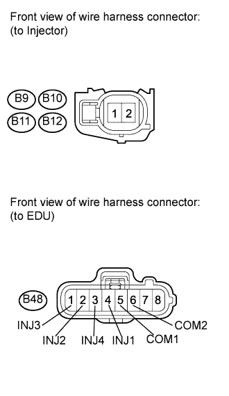
| 9.CHECK HARNESS AND CONNECTOR (INJECTOR - EDU) |
Disconnect the injector connectors.
Disconnect the EDU connector.
Measure the resistance according to the value(s) in the table below.
- Standard resistance (Check for open):
Tester Connection
| Condition
| Specified Condition
|
B9-1 - B48-4 (INJ1)
| Always
| Below 1 Ω
|
B11-1 - B48-2 (INJ2)
| Always
| Below 1 Ω
|
B10-1 - B48-1 (INJ3)
| Always
| Below 1 Ω
|
B12-1 - B48-3 (INJ4)
| Always
| Below 1 Ω
|
B9-2 - B48-5 (COM1)
| Always
| Below 1 Ω
|
B10-2 - B48-6 (COM2)
| Always
| Below 1 Ω
|
B11-2 - B48-6 (COM2)
| Always
| Below 1 Ω
|
B12-2 - B48-5 (COM1)
| Always
| Below 1 Ω
|
- Standard resistance (Check for short):
Tester Connection
| Condition
| Specified Condition
|
B9-1 or B48-4 (INJ1) - Body ground
| Always
| 10 kΩ or higher
|
B11-1 or B48-2 (INJ2) - Body ground
| Always
| 10 kΩ or higher
|
B10-1 or B48-1 (INJ3) - Body ground
| Always
| 10 kΩ or higher
|
B12-1 or B48-3 (INJ4) - Body ground
| Always
| 10 kΩ or higher
|
B9-2 or B48-5 (COM1) - Body ground
| Always
| 10 kΩ or higher
|
B10-2 or B48-6 (COM2) - Body ground
| Always
| 10 kΩ or higher
|
B11-2 or B48-6 (COM2) - Body ground
| Always
| 10 kΩ or higher
|
B12-2 or B48-5 (COM1) - Body ground
| Always
| 10 kΩ or higher
|
Reconnect the injector connectors.
Reconnect the EDU connector.
| | REPAIR OR REPLACE HARNESS OR CONNECTOR (INJECTOR - EDU) |
|
|
| 10.PERFORM ACTIVE TEST BY INTELLIGENT TESTER (CONTROL THE CYLINDER FUEL CUT) |
Connect the intelligent tester to the DLC3.
Start the engine and turn the tester on.
Enter the following menus: Powertrain / Engine and ECT / Active Test / Control the Cylinder #1, #2, #3, and #4 Fuel Cut.
Check the engine idling condition while the fuel injection of each cylinder is cut using the tester.
- Result:
Result
| Proceed to
|
Engine idling condition: Becomes unstable
| A
|
Engine idling condition: Does not change
| B
|
- УКАЗАНИЕ:
- Replace the injector mounted on the cylinder that causes no significant idle speed change.
| 11.READ VALUE USING INTELLIGENT TESTER (ENGINE COOLANT TEMPERATURE) |
Connect the intelligent tester to the DLC3.
Turn the ignition switch on (IG) and turn the tester on.
Enter the following menus: Powertrain / Engine and ECT / Data List / Coolant Temp.
Read the value.
- Standard value:
- Between 75 and 95°C (167 and 203°F) with warm engine
| 12.READ VALUE OF DIESEL TURBO PRESSURE SENSOR |
Connect the intelligent tester to the DLC3.
Turn the ignition switch on (IG) and turn the tester on.
Enter the following menus: Powertrain / Engine and ECT / Data List / MAP and Atmosphere Pressure.
Read the value.
- Standard value:
Condition
| MAP Value
|
No pressure applied
| Same as atmospheric pressure
|
Vacuum applied
| Becomes vacuum
|
Pressure applied
| Becomes pressurized
|
| 13.READ VALUE USING INTELLIGENT TESTER (ENGINE SPEED) |
Connect the intelligent tester to the DLC3.
Turn the ignition switch on (IG) and turn the tester on.
Enter the following menus: Powertrain / Engine and ECT / Data List / Engine Speed.
Read the value.
- Standard value:
- Between 750 and 850 rpm with warm engine (air conditioner switch OFF).
| 14.READ VALUE USING INTELLIGENT TESTER (ACCEL POSITION 1 AND 2) |
Connect the intelligent tester to the DLC3.
Turn the ignition switch on (IG) and turn the tester on.
Enter the following menus: Powertrain / Engine and ECT / Data List / Accel Position 1 and 2.
Read the value.
- Standard voltage:
Accelerator Pedal
| Accelerator Pedal Condition
| Specified Condition
|
Accel Position 1
| Released
| 0.6 to 1.0 V
|
Accel Position 1
| Depressed
| 3.4 to 3.8 V
|
Accel Position 2
| Released
| 1.4 to 1.8 V
|
Accel Position 2
| Depressed
| 4.2 to 4.6 V
|
- УКАЗАНИЕ:
- In the chart above, "Idling" means that the engine should be idled under the following conditions:
- The air conditioner switch is OFF and the shift lever is in the neutral position.
- After the engine is warmed up, the engine has no load.
| 15.READ VALUE USING INTELLIGENT TESTER (INTAKE AIR TEMPERATURE) |
Connect the intelligent tester to the DLC3.
Turn the ignition switch on (IG) and turn the tester on.
Enter the following menus: Powertrain / Engine and ECT / Data List / Intake Air.
Read the value.
- OK:
- Same as air temperature near to intake manifold
- УКАЗАНИЕ:
- In the chart above, "Idling" means that the engine should be idled under the following conditions:
- The air conditioner switch is OFF and the shift lever is in the neutral position.
- After the engine is warmed up, the engine has no load.
| 16.READ VALUE USING INTELLIGENT TESTER (FUEL PRESSURE) |
Connect the intelligent tester to the DLC3.
Turn the ignition switch on (IG) and turn the tester on.
Enter the following menus: Powertrain / Engine and ECT / Data List / Fuel Press.
Read the value.
- Standard value:
- 35 to 45 MPa engine idling
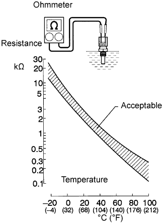
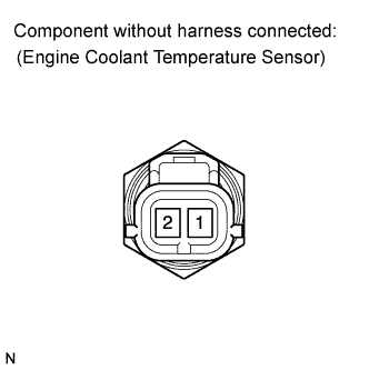
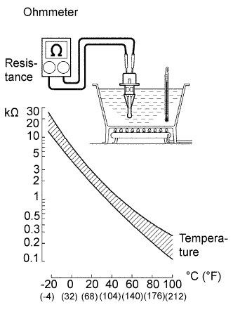
| 17.INSPECT ENGINE COOLANT TEMPERATURE SENSOR |
Disconnect the engine coolant temperature sensor.
Measure the resistance of the sensor.
- Standard resistance:
Tester Connection
| Condition
| Specified Condition
|
1 - 2
| 20°C (68°F)
| 2.32 to 2.59 kΩ
|
1 - 2
| 80°C (176°F)
| 0.310 to 0.326 kΩ
|
- ПРИМЕЧАНИЕ:
- When checking the engine coolant temperature sensor in water, keep the terminals dry. After the check, wipe the sensor dry.
- УКАЗАНИЕ:
- Alternative procedure: Connect an ohmmeter to the installed engine coolant temperature sensor and read the resistance. Use an infrared thermometer to measure the engine temperature in the immediate vicinity of the sensor. Compare these values against the resistance/ temperature graph. Change the engine temperature (warm up or cool down) and repeat the test.
Reconnect the engine coolant temperature sensor.
| OK |
|
|
|
| REPAIR OR REPLACE HARNESS OR CONNECTOR (INJECTOR - EDU) |
|
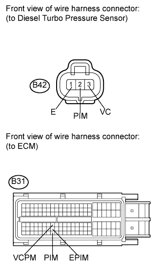
| 18.CHECK HARNESS AND CONNECTOR (DIESEL TURBO PRESSURE SENSOR - ECM) |
Disconnect the diesel turbo pressure sensor connector.
Disconnect the ECM connector.
Measure the resistance according to the value(s) in the table below.
- Standard resistance (Check for open):
Tester Connection
| Condition
| Specified Condition
|
B42-2 (PIM) - B31-117 (PIM)
| Always
| Below 1 Ω
|
B42-3 (VC) - B31-71 (VCPM)
| Always
| Below 1 Ω
|
B42-1 (E) - B31-94 (EPIM)
| Always
| Below 1 Ω
|
- Standard resistance (Check for short):
Tester Connection
| Condition
| Specified Condition
|
B42-2 (PIM) or B31-117 (PIM) - Body ground
| Always
| 10 kΩ or higher
|
B42-3 (VC) or B31-71 (VCPM) - Body ground
| Always
| 10 kΩ or higher
|
B42-1 (E) or B31-94 (EPIM) - Body ground
| Always
| 10 kΩ or higher
|
Reconnect the diesel turbo pressure sensor connector.
Reconnect the ECM connector.
| | REPAIR OR REPLACE HARNESS OR CONNECTOR (DIESEL TURBO PRESSURE SENSOR - ECM) |
|
|
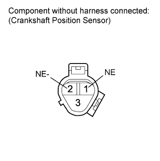
| 19.INSPECT CRANKSHAFT POSITION SENSOR |
Disconnect the crankshaft position sensor connector.
Measure the resistance according to the value(s) in the table below.
- Standard resistance:
Tester Connection
| Condition
| Specified Condition
|
1 (NE) - 2 (NE-)
| 20°C (68°F)
| 950 to 1250 Ω
|
Reconnect the crankshaft position sensor connector.
| OK |
|
|
|
| REPAIR OR REPLACE HARNESS OR CONNECTOR (INJECTOR - EDU) |
|
| 20.CHECK HARNESS AND CONNECTOR (ACCELERATOR PEDAL POSITION SENSOR - ECM) |
Disconnect the accelerator pedal position sensor connector.
Disconnect the ECM connector.
Measure the resistance according to the value(s) in the table below.
- Standard resistance (Check for open):
Tester Connection
| Condition
| Specified Condition
|
A3-1 (VCP2) - A50-56 (VCP2)
| Always
| Below 1 Ω
|
A3-2 (EPA2) - A50-58 (EPA2)
| Always
| Below 1 Ω
|
A3-3 (VPA2) - A50-54 (VPA2)
| Always
| Below 1 Ω
|
A3-4 (VCPA) - A50-55 (VCPA)
| Always
| Below 1 Ω
|
A3-5 (EPA) - A50-57 (EPA)
| Always
| Below 1 Ω
|
A3-6 (VPA) - A50-53 (VPA)
| Always
| Below 1 Ω
|
- Standard resistance (Check for short):
Tester Connection
| Condition
| Specified Condition
|
A3-1 (VCP2) or A50-56 (VCP2) - Body ground
| Always
| 10 kΩ or higher
|
A3-2 (EPA2) or A50-58 (EPA2) - Body ground
| Always
| 10 kΩ or higher
|
A3-3 (VPA2) or A50-54 (VPA2) - Body ground
| Always
| 10 kΩ or higher
|
A3-4 (VCPA) or A50-55 (VCPA) - Body ground
| Always
| 10 kΩ or higher
|
A3-5 (EPA) or A50-57 (EPA) - Body ground
| Always
| 10 kΩ or higher
|
A3-6 (VPA) or A50-53 (VPA) - Body ground
| Always
| 10 kΩ or higher
|
Reconnect the accelerator pedal position sensor connector.
Reconnect the ECM connector.
| | REPAIR OR REPLACE HARNESS OR CONNECTOR (ACCELERATOR PEDAL POSITION SENSOR - ECM) |
|
|
| OK |
|
|
|
| REPLACE ACCELERATOR PEDAL (ACCELERATOR PEDAL POSITION SENSOR) (Нажмите здесь) |
|
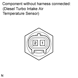
| 21.INSPECT DIESEL TURBO INTAKE AIR TEMPERATURE SENSOR |
Remove the diesel turbo intake air temperature sensor.
Measure the resistance according to the value(s) in the table below.
- Standard resistance:
Tester Connection
| Condition
| Specified Condition
|
1 - 2
| 20°C (68°F)
| 2.21 to 2.65 kΩ
|
- ПРИМЕЧАНИЕ:
- When checking the sensor in water, keep the terminals dry. After the check, wipe the sensor dry.
Reconnect the diesel turbo intake air temperature sensor.
| | REPLACE DIESEL TURBO INTAKE AIR TEMPERATURE SENSOR (Нажмите здесь) |
|
|
| OK |
|
|
|
| REPAIR OR REPLACE HARNESS OR CONNECTOR (INJECTOR - EDU) |
|
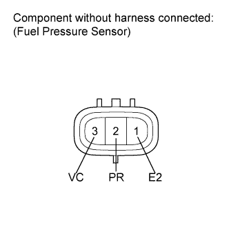
| 22.INSPECT COMMON RAIL ASSEMBLY (FUEL PRESSURE SENSOR) |
Disconnect the fuel pressure sensor connector.
Measure the resistance according to the value(s) in the table below.
- Standard resistance:
Tester Connection
| Condition
| Specified Condition
|
2 (PR) - 1 (E2)
| Always
| 16.4 kΩ or less
|
2 (PR) - 3 (VC)
| Always
| 3 kΩ or less
|
Reconnect the fuel pressure sensor connector.
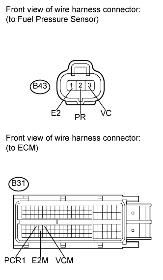
| 23.CHECK HARNESS AND CONNECTOR (FUEL PRESSURE SENSOR - ECM) |
Disconnect the fuel pressure sensor connector.
Disconnect the ECM connector.
Measure the resistance according to the value(s) in the table below.
- Standard resistance (Check for open):
Tester Connection
| Condition
| Specified Condition
|
B43-2 (PR) - B31-67 (PCR1)
| Always
| Below 1 Ω
|
B43-3 (VC) - B31-69 (VCM)
| Always
| Below 1 Ω
|
B43-1 (E2) - B31-91 (E2M)
| Always
| Below 1 Ω
|
- Standard resistance (Check for short):
Tester Connection
| Condition
| Specified Condition
|
B43-2 (PR) or B31-67 (PCR1) - Body ground
| Always
| 10 kΩ or higher
|
B43-3 (VC) or B31-69 (VCM) - Body ground
| Always
| 10 kΩ or higher
|
B43-1 (E2) or B31-91 (E2M) - Body ground
| Always
| 10 kΩ or higher
|
Reconnect the fuel pressure sensor connector.
Reconnect the ECM connector.
| | REPAIR OR REPLACE HARNESS OR CONNECTOR (FUEL PRESSURE SENSOR - ECM) |
|
|
Replace the ECM (See page Нажмите здесь).
- ПРИМЕЧАНИЕ:
- After replacing the ECM, the new ECM needs registration (See page Нажмите здесь) and initialization (See page Нажмите здесь).
Check the volume of black smoke in the exhaust gas.
- OK:
- Black smoke is not present.