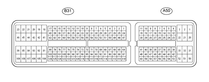
Terminal No. (Symbols)
| Wiring Color
| Terminal Description
| Condition
| Specified Condition
|
A50-2 (BATT) - B31-109 (E1)
| W - W
| Battery (for measuring the battery voltage and for the ECM memory)
| Always
| 11 to 14 V
|
A50-25 (IGSW) - B31-109 (E1)
| B - W
| Ignition switch
| Ignition switch on (IG)
| 11 to 14 V
|
A50-1 (+B) - B31-109 (E1)
| B - W
| Power source of ECM
| Ignition switch on (IG)
| 11 to 14 V
|
A50-45 (MREL) - B31-109 (E1)
| O - W
| EFI relay
| Ignition switch on (IG)
| 11 to 14 V
|
A50-45 (MREL) - B31-109 (E1)
| O - W
| EFI relay
| 2 seconds elapsed after ignition switch off
| 0 to 1.5 V
|
A50-44 (IREL) - B31-109 (E1)
| R - W
| EDU relay
| Ignition switch off
| 9 to 14 V
|
A50-44 (IREL) - B31-109 (E1)
| R - W
| EDU relay
| Idling
| 0 to 1.5 V
|
A50-53 (VPA) - A50-57 (EPA)
| W - Y
| Accelerator pedal position sensor (for engine control)
| Ignition switch on (IG), accelerator pedal fully released
| 0.5 to 1.1 V
|
A50-53 (VPA) - A50-57 (EPA)
| W - Y
| Accelerator pedal position sensor (for engine control)
| Ignition switch on (IG), accelerator pedal fully depressed
| 3.0 to 4.6 V
|
A50-54 (VPA2) - A50-58 (EPA2)
| R - O (*1)
R - P (*2)
| Accelerator pedal position sensor (for sensor malfunction detection)
| Ignition switch on (IG), accelerator pedal fully released
| 0.9 to 2.3 V
|
A50-54 (VPA2) - A50-58 (EPA2)
| R - O (*1)
R - P (*2)
| Accelerator pedal position sensor (for sensor malfunction detection)
| Ignition switch on (IG), accelerator pedal fully depressed
| 3.4 to 5.0 V
|
A50-55 (VCPA) - A50-57 (EPA)
| B - Y
| Power source of accelerator pedal position sensor (for VPA1)
| Ignition switch on (IG)
| 4.5 to 5.5 V
|
A50-56 (VCP2) - A50-58 (EPA2)
| L - O (*1)
L - P (*2)
| Power source of accelerator pedal position sensor (for VPA2)
| Ignition switch on (IG)
| 4.5 to 5.5 V
|
B31-110 (THA) - B31-87 (ETHA)
| P - BR
| Intake air temperature sensor
| Idling, intake air temperature at 0 to 80°C (32 to 176°F)
| 0.5 to 3.4 V
|
B31-111 (THW) - B31-88 (ETHW)
| L - P
| Engine coolant temperature sensor
| Idling, engine coolant temperature at 60 to 120°C (140 to 248°F)
| 0.2 to 1.0 V
|
A50-43 (STA) - B31-109 (E1)
| LG - W
| Starter signal
| Cranking
| 6.0 V or more
|
B31-50 (#1) - B31-109 (E1)
B31-49 (#2) - B31-109 (E1)
B31-48 (#3) - B31-109 (E1)
B31-47 (#4) - B31-109 (E1)
| G - W
B - W
P - W
LG - W
| Injector
| Idling
| Pulse generation
(See waveform 2)
|
B31-52 (PRD) - B31-109 (E1)
| L - W
| Pressure relief valve drive signal
| Ignition switch off
| 4 to 5.5 V
|
B31-62 (IDLO) - B31-109 (E1)
| W - W
| EDU
| Idling
| 4 to 5.5 V
|
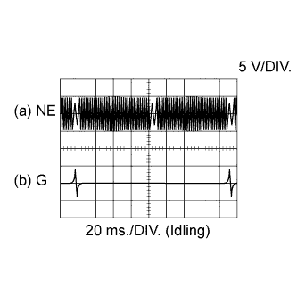
B31-80 (G+) - B31-79 (G-)
| R - G
| Camshaft position sensor
| Idling
| Pulse generation
(See waveform 4)
|
B31-78 (NE+) - B31-77 (NE-)
| G - R
| Crankshaft position sensor
| Idling
| Pulse generation
(See waveform 4)
|
A50-35 (STP) - B31-109 (E1)
| L - W
| Normally open switch
| Ignition switch on (IG), brake pedal depressed
| 11 to 14 V
|
A50-35 (STP) - B31-109 (E1)
| L - W
| Normally open switch
| Ignition switch on (IG), brake pedal released
| 0 to 1.5 V
|
A50-34- (ST1-) - B31-109 (E1)
| R-W (*1) - W
R (*2) - W
| Normally closed switch
| Ignition switch on (IG), brake pedal depressed
| 0 to 1.5 V
|
A50-34 (ST1-) - B31-109 (E1)
| R-W (*1) - W
R (*2) - W
| Normally closed switch
| Ignition switch on (IG), brake pedal released
| 11 to 14 V
|
A50-26 (TC) - B31-109 (E1)
| P - W
| Terminal TC of DLC3
| Ignition switch on (IG)
| 11 to 14 V
|
A50-12 (W) - B31-109 (E1)
| R-B - W
| MIL
| MIL illuminated
| 0 to 3 V
|
A50-12 (W) - B31-109 (E1)
| R-B - W
| MIL
| MIL not illuminated
| 11 to 14 V
|
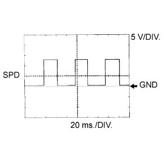
A50-14 (SPD) - B31-109 (E1)
| V - W
| Speed signal from combination meter
| Ignition switch on (IG), drive wheels are rotating slowly
| Pulse generation
(See waveform 7)
|
B31-71 (VCPM) - B31-94 (EPIM)
| W - Y
| Diesel turbo pressure sensor power source
| Ignition switch on (IG)
| 4.5 to 5.5 V
|
B31-117 (PIM) - B31-94 (EPIM)
| GR - Y
| Diesel turbo pressure sensor
| Apply negative pressure of 40 kPa (300 mmHg, 11.8 in.Hg)
| 0.3 to 0.9 V
|
B31-117 (PIM) - B31-94 (EPIM)
| GR - Y
| Diesel turbo pressure sensor
| Same as atmospheric pressure
| 0.8 to 1.4 V
|
B31-117 (PIM) - B31-94 (EPIM)
| GR - Y
| Diesel turbo pressure sensor
| Apply positive pressure of 69 kPa (518 mmHg, 20.3 in.Hg)
| 1.6 to 2.2 V
|
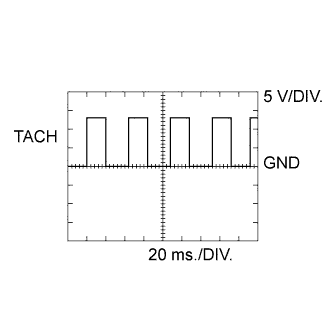
A50-13 (TACH) - B31-109 (E1)
| GR - W
| Engine speed
| Idling
| Pulse generation
(See waveform 8)
|
B31-69 (VCM) - B31-91 (E2M)
| L - BR
| Common rail pressure sensor (main) power source
| Ignition switch on (IG)
| 4.5 to 5.5 V
|
B31-68 (VCS) - B31-66 (E2S)
| R - G
| Common rail pressure sensor
| Ignition switch on (IG)
| 4.5 to 5.5 V
|
B31-67 (PCR1) - B31-91 (E2M)
| W - BR
| Common rail pressure sensor (main)
| Idling
| 1.9 to 2.2 V
|
B31-114 (PCR2) - B31-66 (E2S)
| GR - G
| Common rail pressure sensor (sub)
| Idling
| 1.4 to 1.7 V
|
B31-56 (GREL) - B31-109 (E1)
| B - W
| Glow plug relay
| Cranking
| 11 to 14 V
|
B31-56 (GREL) - B31-109 (E1)
| B - W
| Glow plug relay
| Idling (After engine start, 10 minutes or more have passed)
| 0 to 1.5 V
|
B31-112 (THF) - B31-89 (ETHF)
| GR - P
| Fuel temperature sensor
| Ignition switch on (IG)
| 0.5 to 3.4 V
|
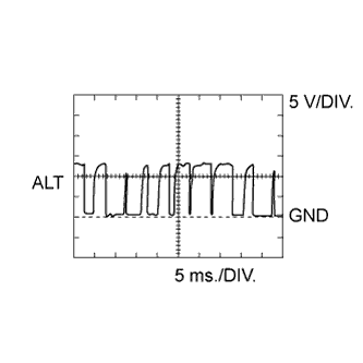
B31-54 (ALT) - B31-109 (E1)
| P - W
| Generator duty ratio
| Idling
| Pulse generation
(See waveform 9)
|
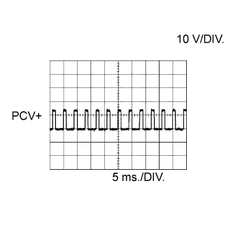
B31-42 (PCV+) - B31-41 (PCV-)
| B - L
| Suction control valve
| Idling
| Pulse generation
(See waveform 1)
|
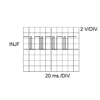
B31-51 (INJF) - B31-109 (E1)
| Y - W
| EDU
| Idling
| Pulse generation
(See waveform 3)
|
B31-73 (VCVL) - B31-96 (EVLU)
| W - BR
| Throttle position sensor power source
| Ignition switch on (IG)
| 4.5 to 5.5 V
|
B31-119 (VLU) - B31-96 (EVLU)
| Y - BR
| Throttle position sensor
| Ignition switch on (IG), throttle valve fully open
| 2.8 to 3.8 V
|
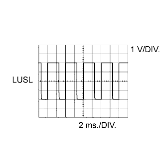
B31-86 (LUSL) - B31-109 (E1)
| L - W
| Throttle valve duty signal
| Engine warmed up, engine racing
| Pulse generation
(See waveform 6)
|
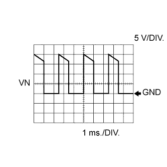
B31-84 (VN) - B31-109 (E1)
| L - W
| VRV (for turbocharger control)
| Idling
| Pulse generation
(See waveform 5)
|
B31-118 (EGLS) - B31-95 (EEGL)
| GR - V
| EGR valve position sensor
| Ignition switch on (IG)
| 0.6 to 1.4 V
|
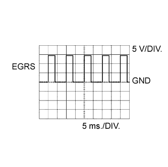
B31-85 (EGRS) - B31-109 (E1)
| W - W
| EGR valve
| Idling
| Pulse generation
(See waveform 10)
|
B31-72 (VCEG) - B31-95 (EEGL)
| P - V
| EGR valve power source
| Ignition switch on (IG)
| 4.5 to 5.5 V
|
B31-113 (THIA) - B31-90 (ETHI)
| P - B
| Intake air temperature sensor (Intake manifold)
| Idling, intake air temperature at 0 to 80°C (32 to 176°F)
| 0.5 to 3.4 V
|
B31-105 (FIV) - B31-109 (E1)
| L - W
| Exhaust fuel addition injector
| Engine warmed up, idling, every 1 to 2 minutes
| Pulse generation
|
B31-121 (THCO) - B31-98 (ETCO)
| R - BR
| Exhaust gas temperature sensor
| Engine warmed up, idling
| 4.6 to 4.9 V
|
B31-122 (THCI) - B31-99 (ETCI)
| L - W
|
B31-120 (PEX) - B31-97 (EPEX)
| G - L
| Differential pressure sensor
| Ignition switch on (IG)
| 0.4 to 4.8 V
|
B31-74 (VCPX) - B31-97 (EPEX)
| R - L
| Differential pressure sensor power source
| Ignition switch on (IG)
| 4.5 to 5.5 V
|
B31-103 (AF2+) - B31-109 (E1)
| L - W
| Air fuel ratio sensor
| Ignition switch on (IG)
| 2.0 to 2.5 V
|
B31-126 (AF2-) - B31-109 (E1)
| P - W
| Air fuel ratio sensor
| Ignition switch on (IG)
| 2.0 to 2.5 V
|
B31-104 (HAF2) - B31-46 (E05)
| W - W
| Air fuel ratio sensor heater
| Ignition switch on (IG)
| 11 to 14 V
|
B31-65 (VG) - B31-64 (EVG)
| GR - LG
| Mass air flow meter power source
| Engine idling
| 0.5 to 3.4 V
|
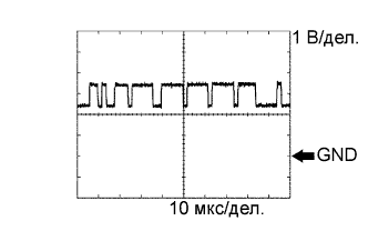
A50-38 (CANH) - B31-109 (E1)
| Y - W
| CAN communication line
| Ignition switch on (IG)
| Pulse generation
(See waveform 11)
|
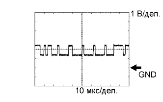
A50-46 (CANL) - B31-109 (E1)
| W - W
| CAN communication line
| Ignition switch on (IG)
| Pulse generation
(See waveform 12)
|
B31-53 (STAR) (*3) - B31-109 (E1)
| W - W
| Starter relay control
| Ignition switch on (IG)
| Below 1.5 V
|
Cranking
| 5.5 V or more
|
A50-22 (FANL) - B31-109 (E1)
| R - W
| FAN NO. 3 relay
| Idling with A/C ON or high engine coolant temperature
| Below 1.5 V
|
A50-21 (FANH) - B31-109 (E1)
| W - W
| FAN NO. 1, 2 relay
| Idling with high engine coolant temperature
| Below 1.5 V
|
A50-24 (ACCR) (*3) - B31-109 (E1)
| L-Y - W
| ACC relay control signal
| Cranking
| Below 1.5 V
|
A50-9 (STSW) (*3) - B31-109 (E1)
| W-G - W
| Starter relay operation signal
| Cranking
| 11 to 14 V
|