Двигатель. COROLLA, AURIS. ZZE150 ZRE151,152 NDE150
Система Управления Двигателем 1Nd-Tv. COROLLA, AURIS. ZZE150 ZRE151,152 NDE150
Система Ecd -- Контакты Ecm |
- УКАЗАНИЕ:
- Each ECM terminal's standard voltage is shown in the table below.
- In the table, first follow the information under "Condition". Look under "Symbols (Terminal No.)" for the terminals to be inspected. The standard voltage between the terminals is shown under "Specified Condition".
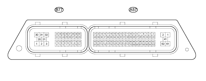
- Use the illustration above as a reference for the ECM terminals.
| Symbols (Terminal No.) | Wiring Color | Terminal Description | Condition | Specified Condition |
| A57-61 (+B) - A57-41 (E1) | B - W-B | Power source of ECM | Ignition switch in the ON position | 9 to 14 V |
| A57-1 (+B1) - A57-41 (E1) | B - W-B | Power source of ECM | Ignition switch in the ON position | 9 to 14 V |
| A57-70 (IGSW) - A57-41 (E1) | B - W-B | Ignition switch | Ignition switch in the ON position | 9 to 14 V |
| A57-42 (MREL) - A57-41 (E1) | B - W-B | EFI MAIN relay | Ignition switch in the ON position | 0 to 1.5 V |
| 20 seconds elapsed after ignition switch off | 9 to 14 V | |||
| A57-81 (GREL) - A57-41 (E1) | L-R - W-B | Glow plug relay | Ignition switch in the ON position at cold engine (Engine coolant temperature is less than 20°C (68°F)) | 0 to 1.5 V |
| Idling with warm engine | 9 to 14 V | |||
| A57-15 (VPA) - A57-54 (EPA) | W - Y | Accelerator pedal position sensor (for engine control) | Ignition switch in the ON position, accelerator pedal fully released | 0.6 to 1.0 V |
| Ignition switch in the ON position, accelerator pedal fully depressed | 3.0 to 4.6 V | |||
| A57-14 (VPA2) - A57-53 (EPA2) | R-L - O | Accelerator pedal position sensor (for sensor malfunction detection) | Ignition switch in the ON position, accelerator pedal fully released | 1.4 to 1.8 V |
| Ignition switch in the ON position, accelerator pedal fully depressed | 3.7 to 5.0 V | |||
| A57-34 (VCPA) - A57-54 (EPA) | B - Y | Power source of accelerator pedal position sensor (for VPA1) | Ignition switch in the ON position | 4.5 to 5.5 V |
| A57-33 (VCP2) - A57-53 (EPA2) | L-W - O | Power source of accelerator pedal position sensor (for VPA2) | Ignition switch in the ON position | 4.5 to 5.5 V |
| B77-36 (VG) - B77-15 (EVG) | B - BR (*1) GR - LG (*2) | Mass air flow meter | Idling | 0.5 to 3.4V |
| B77-7 (THA) - B77-6 (ETHA) | L - BR (*1) P - BR (*2) | Intake air temperature sensor | Idling, intake air temperature at 20°C (68°F) | 0.5 to 3.4 V |
| B77-26 (VCS) - B77-16 (E2S) | R - BR | Power source of sensor (a specific voltage) | Ignition switch in the ON position | 4.5 to 5.5 V |
| B77-37 (PC) - B77-16 (E2S) | W - BR | Common rail pressure sensor | Idling | 1.1 to 1.4 V |
| B77-33 (VN) - A57-41 (E1) | W - W-B (*1) V - W-B (*2) | VRV (for VN turbocharger) | Idling | Pulse generation (See waveform 1) |
| B77-12 (PCV) - A57-41 (E1) | R-B - W-B (*1) R - W-B (*2) | Supply pump (suction control valve) | Idling | Pulse generation (See waveform 2) |
| A57-69 (CLSW) - A57-41 (E1) | W - W-B | Clutch switch | Clutch pedal depressed | 9 to 15 V |
| Clutch pedal released | 0 to 1.5 V | |||
| A57-12 (EGR1) - A57-41 (E1) | R - W-B | EGR valve | Racing engine | Pulse generation (See waveform 3) |
| A57-11 (EGR2) - A57-41 (E1) | G - W-B | |||
| A57-31 (EGR3) - A57-41 (E1) | W - W-B | |||
| A57-30 (EGR4) - A57-41 (E1) | L - W-B | |||
| B77-21 (#10) - B77-1 (INJ1) | B - W (*1) W - R (*2) | Injector | Idling | Pulse generation (See waveform 4) |
| B77-30 (#20) - B77-2 (INJ2) | B - W (*1) B - R (*2) | Injector | Idling | Pulse generation (See waveform 4) |
| B77-31 (#30) - B77-3 (INJ3) | B - W (*1) G - R (*2) | Injector | Idling | Pulse generation (See waveform 4) |
| B77-32 (#40) - B77-20 (INJ4) | B - W (*1) L - R (*2) | Injector | Idling | Pulse generation (See waveform 4) |
| B77-39 (THF) - B77-18 (ETHF) | GR - BR | Fuel temperature sensor | Idling | 0.5 to 3.4 V |
| B77-40 (THW) - B77-29 (ETHW) | B - BR | ECT sensor | Idling, engine coolant temperature at 80°C (176°F) | 0.2 to 1.0 V |
| B77-5 (ALT) - A57-41 (E1) | L - W-B (*1) P - W-B (*2) | Generator (Alternator) duty ratio | Idling | Pulse generation |
| B77-13 (LUSL) - A57-41 (E1) | Y - W-B (*1) L - W-B (*2) | Intake shutter duty signal | Racing engine | Pulse generation (See waveform 5) |
| B77-4 (PRV) - A57-41 (E1) | W-R - W-B (*1) W - W-B (*2) | Pressure control valve signal | Drive vehicle at 50 km/h (31 mph) with third gear, and then decelerate by releasing accelerator pedal | Pulse generation (See waveform 6) |
| B77-23 (G1) - B77-34 (EG) | G - R-W (*1) R - G (*2) | Camshaft position sensor | Idling | Pulse generation (See waveform 7) |
| B77-10 (NE+) - B77-11 (NE-) | B - W (*1) L - P (*2) | Crankshaft position sensor | Idling | Pulse generation (See waveform 7) |
| B77-28 (VVLU) - B77-14 (EVLU) | V - BR (*1) W - BR (*2) | Power source of sensor (a specific voltage) | Ignition switch in the ON position | 4.5 to 5.5 V |
| B77-35 (VLU) - B77-14 (EVLU) | G - BR (*1) Y - BR (*2) | Intake shutter position sensor | Ignition switch in the ON position, intake shutter fully opened | 3.5 to 4.5 V |
| Ignition switch in the ON position, intake shutter fully closed | 0.4 to 1.0 V | |||
| B77-38 (PIM) - B77-17 (EPIM) | G - BR (*1) GR - Y (*2) | Manifold absolute pressure sensor | Ignition switch in the ON position (Same as atmospheric pressure) | 2.0 to 2.6 V |
| B77-27 (VPIM) - B77-17 (EPIM) | V - BR (*1) V - Y (*2) | Power source of sensor (a specific voltage) | Ignition switch in the ON position | 4.5 to 5.5 V |
| A57-20 (TACH) - A57-41 (E1) | GR - W-B | Engine speed | Idling | Pulse generation |
| A57-8 (STP) - A57-41 (E1) | L - W-B | Stop light switch | Brake pedal depressed | 7.5 to 14 V |
| Brake pedal released | 0 to 1.5 V | |||
| A57-27 (ST1-) - A57-41 (E1) | R (M/T) - W-B R-W (MMT) - W-B | Stop light switch (opposite to STP) | Ignition switch in the ON position, brake pedal depressed | 0 to 1.5 V |
| Ignition switch in the ON position, brake pedal released | 7.5 to 14 V | |||
| A57-28 (TC) - A57-41 (E1) | P - W-B | Terminal TC of DLC3 | Ignition switch in the ON position | 9 to 14 V |
| A57-5 (SIL) - A57-41 (E1) | W - W-B | Terminal SIL of DLC3 | Intelligent tester connected to DLC3 | Pulse generation |
| A57-66 (SPD) - A57-41 (E1) | V - W-B | Speed signal from combination meter | Ignition switch in the ON position, driving wheel rotating slowly | Pulse generation (See waveform 8) |
| A57-9 (STA) - A57-41 (E1) | LG - W-B | Starter signal | Cranking | 6.0 V or more |
| A57-23 (W) - A57-41 (E1) | R - W-B | MIL | MIL illuminated | 0 to 3 V |
| MIL not illuminated | 9 to 14 V | |||
| A57-10 (ELS) - A57-41 (E1) | G - W-B | Electric load | Tail light switch on | 7.5 to 14 V |
| Tail light switch off | Below 1.5 V | |||
| A57-68 (ELS2) - A57-41 (E1) | B - W-B | Electric load | Defogger switch on | 7.5 to 14 V |
| Defogger switch off | Below 1.5 V | |||
| A57-22 (NEO) - A57-41 (E1) | Y-B - W-B | Crankshaft position sensor | Engine idling | Pulse generation (See waveform 11) |
| A57-3 (RFC) - A57-41 (E1) | R-G - W-B | Cooling fan control | Ignition switch in the ON position | 4.5 to 5.5 V |
| A57-7 (R) - A57-41 (E1) | R - W-B | Buck-up light switch signal | Buck-up light switch on | 9 to 14 V |
| A57-46 (MHSW) - A57-41 (E1) | Y - W-B | Power heater switch signal | Power heater switch on | 9 to 14 V |
| A57-43 (CAN+) - A57-41 (E1) | R - W-B | CAN communication line | Ignition switch in the ON position | Pulse generation (See waveform 9) |
| A57-64 (CAN-) - A57-41 (E1) | W - W-B | CAN communication line | Ignition switch in the ON position | Pulse generation (See waveform 10) |
| A57-24 (CANH) - A57-41 (E1) | Y - W-B | CAN communication line | Ignition switch in the ON position | Pulse generation (See waveform 9) |
| A57-44 (CANL) - A57-41 (E1) | W - W-B | CAN communication line | Ignition switch in the ON position | Pulse generation (See waveform 10) |
| A57-41 (E1) - Body ground | W-B - - | Ground | Always | Below 1 Ω |
| A57-62 (E2) - Body ground | W-B - - | Ground | Always | Below 1 Ω |
| A57-2 (E11) - Body ground | W-B - - | Ground | Always | Below 1 Ω |
*2: Except TMC made
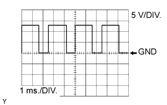
| Waveform 1 |
VRV for turbocharger signal
Symbols (Terminal No.) B77-33 (VN) - A57-41 (E1) Tool setting 5 V/DIV., 1 ms./DIV. Condition Idling with warm engine - УКАЗАНИЕ:
- The waveform varies depending on the VRV for turbocharger operation.
 |
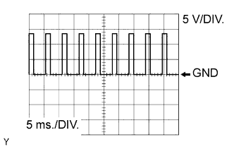
| Waveform 2 |
Suction control valve signal
Symbols (Terminal No.) B77-12 (PCV) - A57-41 (E1) Tool Setting 5 V/DIV., 5 ms./DIV. Condition Idling or cranking with warm engine - УКАЗАНИЕ:
- The waveform varies depending on the suction control valve operation.
 |
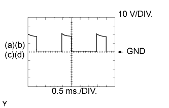
| Waveform 3 |
EGR valve signal
Symbols (Terminal No.) (a) A57-12 (EGR1) - A57-41 (E1)
(b) A57-11 (EGR2) - A57-41 (E1)
(c) A57-31 (EGR3) - A57-41 (E1)
(d) A57-30 (EGR4) - A57-41 (E1)Tool Setting 10 V/ DIV., 0.5 ms./DIV. Condition Repeating quick engine RPM accelerations - УКАЗАНИЕ:
- The waveform varies depending on the EGR valve operation.
- When driving conditions become stable (e.g. while the engine is idling), the EGR valve closes and the waveform may disappear.
 |
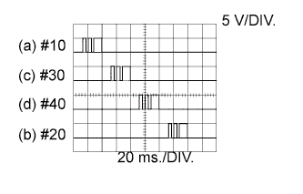
| Waveform 4 |
Injector No. 1 injection signal
Injector No. 2 injection signal
Injector No. 3 injection signal
Injector No. 4 injection signal
Symbols (Terminal No.) (a) B77-21 (#10) - B77-1 (INJ1)
(b) B77-30 (#20) - B77-2 (INJ2)
(c) B77-31 (#30) - B77-3 (INJ3)
(d) B77-32 (#40) - B77-20 (INJ4)Tool Setting 5 V/DIV., 20 ms./DIV. Condition Idling with warm engine - УКАЗАНИЕ:
- The waveform varies depending on the injector injection.
 |
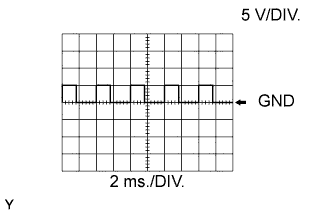
| Waveform 5 |
Intake shutter signal
Symbols (Terminal No.) B77-13 (LUSL) - A57-41 (E1) Tool setting 5 V/DIV., 2 ms./DIV. Condition Idling with warm engine - УКАЗАНИЕ:
- The waveform varies depending on the intake shutter operation.
 |
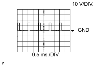
| Waveform 6 |
Pressure control valve signal
Symbols (Terminal No.) B77-4 (PRV) - A57-41 (E1) Tool setting 10 V/DIV., 0.5 ms./DIV. Condition Idling with warm engine - УКАЗАНИЕ:
- The waveform varies depending on the pressure discharge valve operation.
 |
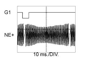
| Waveform 7 |
Crankshaft position sensor signal
Camshaft position sensor signal
Symbol (Terminal No.) Crankshaft position sensor: B77-10 (NE+) - B77-11 (NE-)
Camshaft position sensor: B77-23 (G1) - B77-34 (EG)Tool Setting 10 ms./DIV. Condition Idling with warm engine - УКАЗАНИЕ:
- The waveform varies depending on the engine revolution.
 |
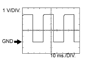
| Waveform 8 |
Vehicle speed signal
Symbols (Terminal No.) A57-66 (SPD) - A57-41 (E1) Tool Setting 1 V/DIV., 10 ms./DIV. Condition While driving the vehicle - УКАЗАНИЕ:
- The wavelength becomes shorter as the vehicle speed increases.
 |
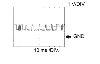
| Waveform 9 |
CAN communication signal
Symbols (Terminal No.) A57-24 (CANH), A57-43 (CAN+) - A57-41 (E1) Tool Setting 1 V/DIV., 10 ms./DIV. Condition Engine stopped, ignition switch in the ON position - УКАЗАНИЕ:
- The wavelength becomes shorter depending on the CAN communication signal.
 |
| Waveform 10 |
CAN communication signal
Symbols (Terminal No.) A57-44 (CANL), A57-64 (CAN-) - A57-41 (E1) Tool Setting 1 V/DIV., 10 ms./DIV. Condition Engine stopped, ignition switch in the ON position - УКАЗАНИЕ:
- The waveform varies depending on the CAN communication signal.
 |
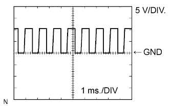
| Waveform 11 |
Crankshaft position sensor
Symbols (Terminal No.) A57-22 (NEO) - A57-41 (E1) Tool Setting 5 V/DIV., 1 ms./DIV. Condition Engine idling - УКАЗАНИЕ:
- The waveform varies depending on the crankshaft position signal.
 |