Dtc P0335 Crankshaft Position Sensor A Circuit. Corolla Auris
Двигатель. COROLLA, AURIS. ZZE150 ZRE151,152 NDE150
DESCRIPTION
WIRING DIAGRAM
INSPECTION PROCEDURE
READ VALUE USING INTELLIGENT TESTER (ENGINE SPEED)
INSPECT CRANKSHAFT POSITION SENSOR (RESISTANCE)
CHECK HARNESS AND CONNECTOR (CRANKSHAFT POSITION SENSOR - ECM)
CHECK SENSOR INSTALLATION (CRANKSHAFT POSITION SENSOR)
CHECK CRANKSHAFT POSITION SENSOR PLATE (TEETH OF SENSOR PLATE)
DTC P0335 Crankshaft Position Sensor "A" Circuit |
DTC P0339 Crankshaft Position Sensor "A" Circuit Intermittent |
DESCRIPTION
The crankshaft position sensor system consists of a crankshaft position sensor plate and a pickup coil. The sensor plate has 34 teeth and is installed on the crankshaft. The pickup coil is made of wound copper wire, an iron core and magnet.The sensor plate rotates and, as each tooth passes through the pickup coil, a pulse signal is created. The pickup coil generates 34 signals per engine revolution. Based on these signals, the ECM calculates the crankshaft position and engine RPM. Using these calculations, the fuel injection time and ignition timing are controlled.DTC No.
| DTC Detection Condition
| Trouble Area
|
P0335
| When either condition below is met:
- No crankshaft position sensor signal to ECM while cranking (1 trip detection logic)
- No crankshaft position sensor signal to ECM at engine speed of 600 rpm or more (1 trip detection logic)
| - Open or short in crankshaft position sensor circuit
- Crankshaft position sensor
- Crankshaft position sensor plate
- ECM
|
P0339
| Under conditions (a), (b) and (c), no crankshaft position sensor signal to ECM for 0.05 seconds or more
(1 trip detection logic):
(a) Engine speed 1000 rpm or more
(b) Starter signal OFF
(c) 3 seconds or more have elapsed since starter signal switched from ON to OFF
| - Open or short in crankshaft position sensor circuit
- Crankshaft position sensor
- Crankshaft position sensor plate
- ECM
|
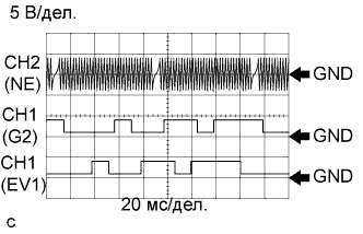
- Reference: Inspection using an oscilloscope.
- УКАЗАНИЕ:
- The correct waveform is as shown.
- G2 stands for the crankshaft position sensor signal, and NE+ stands for the crankshaft position sensor signal.
- Grounding failure of the shielded wire may cause noise in waveforms.
Item
| Content
|
Terminals
| CH1: G2+ - G2-
CH2: NE+ - NE-
|
Equipment Settings
| 5 V/DIV.
20 ms./DIV.
|
Conditions
| Cranking or idling
|
WIRING DIAGRAM
INSPECTION PROCEDURE
- УКАЗАНИЕ:
- If no problem is found through this diagnostic troubleshooting procedure, troubleshoot the engine mechanical system.
- Check the engine speed. The engine speed can be checked by using the intelligent tester. Follow the procedure below:
- Connect the intelligent tester to the DLC3.
- Start the engine.
- Turn the tester on.
- Select the following menu items: Powertrain / Engine and ECT / Data List / Engine Speed.
- The engine speed may be indicated as zero despite the engine revolving normally. This is caused by a lack of NE signals from the crankshaft position sensor. Alternatively, the engine speed may be indicated as lower than the actual engine speed if the crankshaft position sensor output voltage is insufficient.
- Read freeze frame data using the intelligent tester. The ECM records vehicle and driving condition information as freeze frame data the moment a DTC is stored. When troubleshooting, freeze frame data can help determine if the vehicle was moving or stationary, if the engine was warmed up or not, if the air fuel ratio was lean or rich, and other data from the time the malfunction occurred.
| 1.READ VALUE USING INTELLIGENT TESTER (ENGINE SPEED) |
Connect the intelligent tester to the DLC3.
Turn the ignition switch on (IG).
Turn the tester on.
Select the following menu items: Powertrain / Engine and ECT / Data List / Engine Speed.
Start the engine.
Read the values displayed on the tester while the engine is running.
- OK:
- Correct values are displayed.
- УКАЗАНИЕ:
- To check the engine speed change, display the graph on the tester.
- If the engine does not start, check the engine speed while cranking.
- If the engine speed indicated on the tester remains zero(0), there may be an open or short in the crankshaft position sensor circuit.
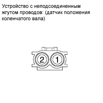
| 2.INSPECT CRANKSHAFT POSITION SENSOR (RESISTANCE) |
Disconnect the crankshaft position sensor connector.
Measure the resistance according to the value(s) in the table below.
- Standard resistance:
Tester Connection
| Condition
| Specified Condition
|
1 - 2
| 20°C (68°F)
| 1850 to 2450 Ω
|
Reconnect the crankshaft position sensor connector.
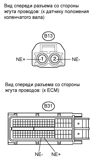
| 3.CHECK HARNESS AND CONNECTOR (CRANKSHAFT POSITION SENSOR - ECM) |
Disconnect the crankshaft position sensor connector.
Disconnect the ECM connector.
Measure the resistance according to the value(s) in the table below.
- Standard resistance (Check for open):
Tester Connection
| Condition
| Specified Condition
|
B13-1 (NE+) - B31-122 (NE+)
| Always
| Below 1 Ω
|
B13-2 (NE-) - B31-121 (NE-)
| Always
| Below 1 Ω
|
- Standard resistance (Check for short):
Tester Connection
| Condition
| Specified Condition
|
B13-1 (NE+) or B31-122 (NE+) - Body ground
| Always
| 10 kΩ or higher
|
B13-2 (NE-) or B31-121 (NE-) - Body ground
| Always
| 10 kΩ or higher
|
Reconnect the ECM connector.
Reconnect the crankshaft position sensor connector.
| | REPAIR OR REPLACE HARNESS OR CONNECTOR (CRANKSHAFT POSITION SENSOR - ECM) |
|
|
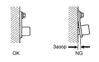
| 4.CHECK SENSOR INSTALLATION (CRANKSHAFT POSITION SENSOR) |
Check the crankshaft position sensor installation condition.
- OK:
- Sensor is installed correctly.
| 5.CHECK CRANKSHAFT POSITION SENSOR PLATE (TEETH OF SENSOR PLATE) |
Check the teeth of the sensor plate (See page Нажмите здесь).
- OK:
- Sensor plate does not have any cracks or deformation.