Двигатель. COROLLA, AURIS. ZZE150 ZRE151,152 NDE150
DESCRIPTION
WIRING DIAGRAM
INSPECTION PROCEDURE
CHECK IF VEHICLE IS EQUIPPED WITH ENTRY AND START SYSTEM
READ VALUE OF INTELLIGENT TESTER (STARTER SIGNAL)
INSPECT IGNITION SWITCH ASSEMBLY
CHECK HARNESS AND CONNECTOR (IGNITION SWITCH ASSEMBLY - CLUTCH PEDAL SWITCH ASSEMBLY)
CHECK HARNESS AND CONNECTOR (CLUTCH PEDAL SWITCH ASSEMBLY - ST RELAY)
CHECK HARNESS AND CONNECTOR (CLUTCH PEDAL SWITCH ASSEMBLY - ECM)
CHECK HARNESS AND CONNECTOR (PARK/NEUTRAL POSITION SWITCH - ST RELAY)
CHECK HARNESS AND CONNECTOR (ECM - ST RELAY)
READ VALUE OF INTELLIGENT TESTER (STARTER SIGNAL)
CHECK HARNESS AND CONNECTOR (ST CUT RELAY - CLUTCH PEDAL SWITCH ASSEMBLY)
CHECK HARNESS AND CONNECTOR (ST CUT RELAY - MAIN BODY ECU)
CHECK HARNESS AND CONNECTOR (CLUTCH PEDAL SWITCH ASSEMBLY - ST RELAY)
CHECK HARNESS AND CONNECTOR (CLUTCH PEDAL SWITCH ASSEMBLY - ECM)
CHECK HARNESS AND CONNECTOR (PARK/NEUTRAL POSITION SWITCH - ST RELAY)
CHECK HARNESS AND CONNECTOR (PARK/NEUTRAL POSITION SWITCH - ECM)
DTC P0617 Starter Relay Circuit High |
DESCRIPTION
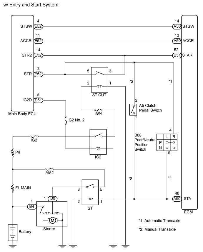
| w/ Entry and Start System |
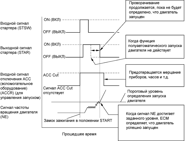
The cranking holding control system keeps energizing the ST relay after the ECM detects the starter signal (STSW signal) from the main body ECU until the ECM performs a judgment of "Engine started". Furthermore, the ECM outputs an accessory cut signal (ACCR signal) to the ACC relay during cranking to prevent flickering of the combination meter, clock, audio system, and so on.
When the ECM detects the STSW signal, the ECM outputs the starter relay drive signal (STAR signal) to the starter relay through the clutch pedal switch or park/neutral position switch, and then, the engine is cranked. When the ECM receives a stable engine speed signal (NE signal), more specifically, when the NE signal reaches a predetermined value, the ECM stops outputting the STAR signal. Also, the ECM monitors the ST relay operating conditions based on the STA terminal voltage status.
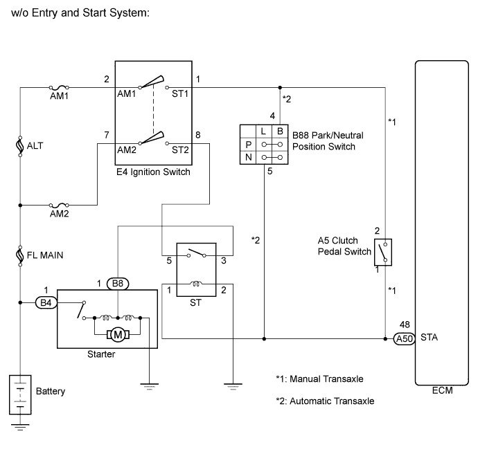
| w/o Entry and Start System |
While the engine is being cranked, the positive battery voltage is applied to terminal STA of the ECM.
If the ECM detects the Starter Control (STA) signal while the vehicle is being driven, it determines that there is a malfunction in the STA circuit. The ECM then illuminates the MIL and sets the DTC.
This monitor runs when the vehicle is driven at 20 km/h (12.4 mph) for over 20 seconds.
DTC No.
| DTC Detection Condition
| Trouble Area
|
P0617
| When conditions (a), (b) and (c) are met, positive (+B) battery voltage 10.5 V or more is applied to ECM for 20 seconds (1 trip detection logic):
- (a) Vehicle speed is more than 20 km/h (12.4 mph)
- (b) Engine speed is more than 1000 rpm
- (c) STA signal is ON
| - Short in cranking holding function circuit*1
- Short in starter signal circuit*2
- Ignition switch*2
- ECM
|
- *1: w/ Entry and Start System
- *2: w/o Entry and Start System
WIRING DIAGRAM
INSPECTION PROCEDURE
- УКАЗАНИЕ:
- The following troubleshooting flowchart is based on the premise that the engine is cranked normally.
If the engine will not crank, proceed to the problem symptoms table (See page Нажмите здесь).
- Read freeze frame data using the intelligent tester. The ECM records vehicle and driving condition information as freeze frame data the moment a DTC is stored. When troubleshooting, freeze frame data can help determine if the vehicle was moving or stationary, if the engine was warmed up or not, and other data from the time the malfunction occurred.
| 1.CHECK IF VEHICLE IS EQUIPPED WITH ENTRY AND START SYSTEM |
- Result:
Result
| Proceed to
|
w/o Entry and Start System
| A
|
w/ Entry and Start System
| B
|
| 2.READ VALUE OF INTELLIGENT TESTER (STARTER SIGNAL) |
Connect the intelligent tester to the DLC3.
Turn the ignition switch on (IG) and turn the tester on.
Select the following menu items: Powertrain / Engine and ECT / Data List / Starter Signal.
Read the value displayed on the tester when the ignition switch is turned on (IG) and engine start.
- OK:
Ignition Switch Condition
| Starter Signal
|
ON (IG)
| OFF
|
Engine Start
| ON
|
- Result:
Result
| Proceed to
|
OK
| A
|
NG (Manual transaxle)
| B
|
NG (Automatic transaxle)
| C
|
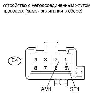
| 3.INSPECT IGNITION SWITCH ASSEMBLY |
Disconnect the ignition switch assembly connector.
Measure the resistance according to the value(s) in the table below.
- Standard resistance:
Tester Connection
| Ignition Switch Position
| Specified Condition
|
All terminals
| LOCK
| 10 kΩ or higher
|
E4-2 (AM1) - E4-1 (ST1)
| START
| Below 1 Ω
|
Reconnect the ignition switch assembly connector.
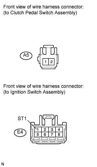
| 4.CHECK HARNESS AND CONNECTOR (IGNITION SWITCH ASSEMBLY - CLUTCH PEDAL SWITCH ASSEMBLY) |
Disconnect the clutch pedal switch assembly connector.
Disconnect the ignition switch assembly connector.
Measure the resistance according to the value(s) in the table below.
- Standard resistance (Check for short):
Tester Connection
| Condition
| Specified Condition
|
E4-1 (ST1) or A5-2 - Body ground
| Always
| 10 kΩ or higher
|
Reconnect the clutch pedal switch assembly connector.
Reconnect the ignition switch assembly connector.
| | REPAIR OR REPLACE HARNESS OR CONNECTOR (IGNITION SWITCH ASSEMBLY - CLUTCH PEDAL SWITCH ASSEMBLY) |
|
|
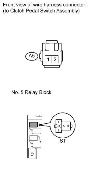
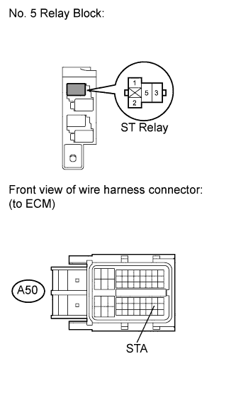
| 5.CHECK HARNESS AND CONNECTOR (CLUTCH PEDAL SWITCH ASSEMBLY - ST RELAY) |
Disconnect the clutch pedal switch assembly connector.
Remove the ST relay from the No. 5 relay block.
Measure the resistance according to the value(s) in the table below.
- Standard resistance (Check for short):
Tester Connection
| Condition
| Specified Condition
|
ST Relay terminal 1 or A5-1 - Body ground
| Always
| 10 kΩ or higher
|
Reconnect the clutch pedal switch assembly connector.
Reinstall the ST relay.
| | REPAIR OR REPLACE HARNESS OR CONNECTOR (CLUTCH PEDAL SWITCH ASSEMBLY - ST RELAY) |
|
|
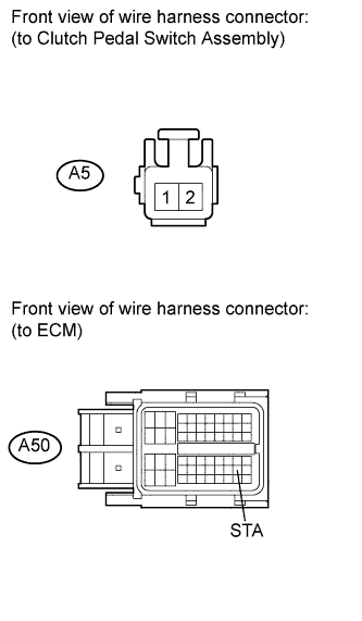
| 6.CHECK HARNESS AND CONNECTOR (CLUTCH PEDAL SWITCH ASSEMBLY - ECM) |
Disconnect the ECM connector.
Disconnect the clutch pedal switch assembly connector.
Measure the resistance according to the value(s) in the table below.
- Standard resistance (Check for short):
Tester Connection
| Condition
| Specified Condition
|
A5-1 or A50-48 (STA) - Body ground
| Always
| 10 kΩ or higher
|
Reconnect the ECM connector.
Reconnect the clutch pedal switch assembly connector.
| | REPAIR OR REPLACE HARNESS OR CONNECTOR (CLUTCH PEDAL SWITCH ASSEMBLY - ECM) |
|
|
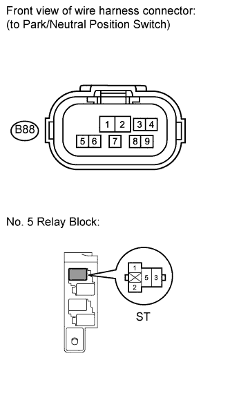
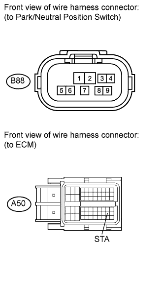
| 7.CHECK HARNESS AND CONNECTOR (PARK/NEUTRAL POSITION SWITCH - ST RELAY) |
Disconnect the park/neutral position switch connector.
Remove the ST relay from the No. 5 relay block.
Measure the resistance according to the value(s) in the table below.
- Standard resistance (Check for short):
Tester Connection
| Condition
| Specified Condition
|
B88-5 - ST Relay terminal 1
| Always
| 10 kΩ or higher
|
Reconnect the park/neutral position switch connector.
Reinstall the ST relay.
| | REPAIR OR REPLACE HARNESS OR CONNECTOR (PARK/NEUTRAL POSITION SWITCH - ST RELAY) |
|
|
| 8.CHECK HARNESS AND CONNECTOR (ECM - ST RELAY) |
Remove the ST relay from the No. 5 relay block.
Disconnect the ECM connector.
Measure the resistance according to the value(s) in the table below.
- Standard resistance (Check for short):
Tester Connection
| Condition
| Specified Condition
|
ST relay terminal 1 or A50-48 (STA) - Body ground
| Always
| 10 kΩ or higher
|
Reinstall the ST relay.
Reconnect the ECM connector.
| | REPAIR OR REPLACE HARNESS OR CONNECTOR (ECM - ST RELAY) |
|
|
| 9.READ VALUE OF INTELLIGENT TESTER (STARTER SIGNAL) |
Connect the intelligent tester to the DLC3.
Turn the ignition switch on (IG) and turn the tester on.
Select the following menu items: Powertrain / Engine and ECT / Data List / Starter Signal.
Read the value displayed on the tester when the ignition switch is turned on (IG).
- OK:
Switch Condition
| Starter Signal
|
Ignition switch on (IG)
| OFF
|
- Result:
Result
| Proceed to
|
OK
| A
|
NG (Manual transaxle)
| B
|
NG (Automatic transaxle)
| C
|
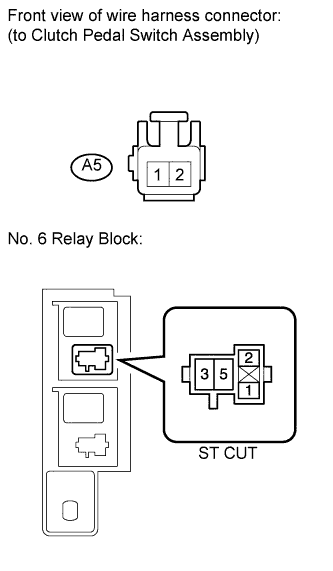
| 10.CHECK HARNESS AND CONNECTOR (ST CUT RELAY - CLUTCH PEDAL SWITCH ASSEMBLY) |
Remove the ST CUT relay from the No. 6 relay block.
Disconnect the clutch pedal switch assembly connector.
Measure the resistance according to the value(s) in the table below.
- Standard resistance (Check for short):
Tester Connection
| Condition
| Specified Condition
|
ST CUT relay terminal 5 or A5-2 - Body ground
| Always
| 10 kΩ or higher
|
Reinstall the relay.
Reconnect the clutch pedal switch assembly connector.
| | REPAIR OR REPLACE HARNESS OR CONNECTOR (ST CUT RELAY - CLUTCH PEDAL SWITCH ASSEMBLY) |
|
|
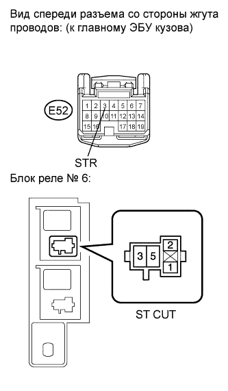
| 11.CHECK HARNESS AND CONNECTOR (ST CUT RELAY - MAIN BODY ECU) |
Remove the ST CUT relay from the No. 6 relay block.
Disconnect the main body ECU connector.
Measure the resistance according to the value(s) in the table below.
- Standard resistance (Check for short):
Tester Connection
| Condition
| Specified Condition
|
ST CUT relay terminal 5 or E52-3 (STR) - Body ground
| Always
| 10 kΩ or higher
|
Reinstall the relay.
Reconnect the main body ECU connector.
| | REPAIR OR REPLACE HARNESS OR CONNECTOR (ST CUT RELAY - MAIN BODY ECU) |
|
|
| 12.CHECK HARNESS AND CONNECTOR (CLUTCH PEDAL SWITCH ASSEMBLY - ST RELAY) |
Remove the ST relay from the No. 5 relay block.
Disconnect the clutch pedal switch assembly connector.
Measure the resistance according to the value(s) in the table below.
- Standard resistance (Check for short):
Tester Connection
| Condition
| Specified Condition
|
ST relay terminal 1 or A5-1 - Body ground
| Always
| 10 kΩ or higher
|
Reinstall the ST relay.
Reconnect the clutch pedal switch assembly connector.
| | REPAIR OR REPLACE HARNESS OR CONNECTOR (CLUTCH PEDAL SWITCH ASSEMBLY - ST RELAY) |
|
|
| 13.CHECK HARNESS AND CONNECTOR (CLUTCH PEDAL SWITCH ASSEMBLY - ECM) |
Disconnect the ECM connector.
Disconnect the clutch pedal switch assembly connector.
Measure the resistance according to the value(s) in the table below.
- Standard resistance (Check for short):
Tester Connection
| Condition
| Specified Condition
|
A50-48 (STA) or A5-1 - Body ground
| Always
| 10 kΩ or higher
|
Reinstall the ECM connector.
Reconnect the clutch pedal switch assembly connector.
| | REPAIR OR REPLACE HARNESS OR CONNECTOR (CLUTCH PEDAL SWITCH ASSEMBLY - ECM) |
|
|
| 14.CHECK HARNESS AND CONNECTOR (PARK/NEUTRAL POSITION SWITCH - ST RELAY) |
Disconnect the park/neutral position switch connector.
Remove the ST relay from the No. 5 relay block.
Measure the resistance according to the value(s) in the table below.
- Standard resistance (Check for short):
Tester Connection
| Condition
| Specified Condition
|
ST relay terminal 1 or A88-5 - Body ground
| Always
| 10 kΩ or higher
|
Reconnect the park/neutral position switch connector.
Reinstall the relay.
| | REPAIR OR REPLACE HARNESS OR CONNECTOR (PARK/NEUTRAL POSITION SWITCH - ST RELAY) |
|
|
| 15.CHECK HARNESS AND CONNECTOR (PARK/NEUTRAL POSITION SWITCH - ECM) |
Disconnect the park/neutral position switch connector.
Disconnect the ECM connector.
Measure the resistance according to the value(s) in the table below.
- Standard resistance (Check for short):
Tester Connection
| Condition
| Specified Condition
|
B88-5 or A50-48 (STA) - Body ground
| Always
| 10 kΩ or higher
|
Reconnect the park/neutral position switch connector.
Reconnect the ECM connector.
| | REPAIR OR REPLACE HARNESS OR CONNECTOR (PARK/NEUTRAL POSITION SWITCH - ECM) |
|
|