Стартер (Для 1,1 Квт) -- Проверка |
| 1. INSPECT STARTER ASSEMBLY |
- ПРИМЕЧАНИЕ:
- Perform each of the following tests within 3 to 5 seconds.
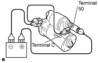
Perform a pull-in test.
Disconnect the field coil lead wire from terminal C.
Connect the battery to the magnet starter switch assembly as shown in the illustration and check that the pinion gear is extended.
If the clutch pinion gear does not move, replace the starter magnetic switch assembly.
 |
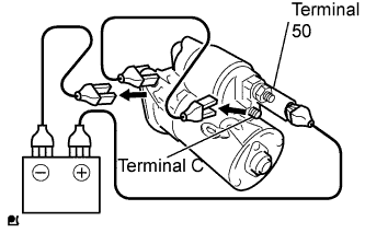
Perform a holding test.
Check that the pinion gear does not return inward after the cable of terminal C is disconnected.
If the clutch pinion gear returns inward, replace the starter magnetic switch assembly.
 |
Inspect the clutch pinion gear return.
Move the pinion gear toward the armature.
If the clutch pinion gear does not return inward, replace the starter magnetic switch assembly.
 |
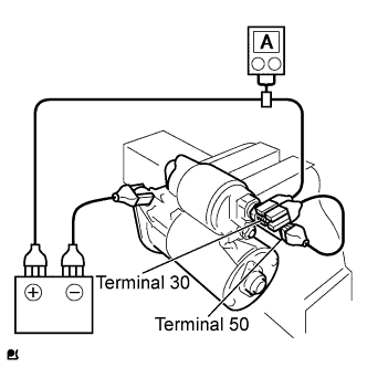
Perform an operation test without load.
Connect the field coil lead wire to terminal C.
- Момент затяжки:
- 8.0 Н*м{82 кгс*см, 71 фунт-сила-дюймов}
Clamp the starter in a vise.
Connect the battery and ammeter to the starter as shown in the illustration.
Check that the ammeter indicates the specified current.
- Standard current:
- 90 A or less at 11.5 V
 |
| 2. INSPECT STARTER ARMATURE ASSEMBLY |
Check the commutator for an open circuit.
Using an ohmmeter, measure the resistance between the segments of the commutator.
- Standard resistance:
- Below 1 Ω
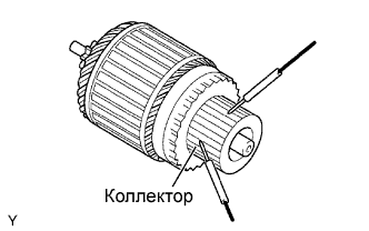 |
Check the commutator for ground.
Using an ohmmeter, measure the resistance between the commutator and the armature coil.
- Standard resistance:
- 10 kΩ or higher
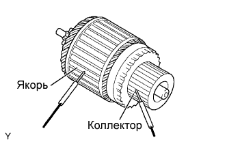 |
Check the commutator for dirt and/or burns on the surface.
If the surface is dirty or burnt, restore it with sandpaper (No. 400) or a lathe.
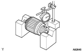
Check the commutator for circle runout.
Place the commutator on V-blocks.
Using a dial indicator, measure the circle runout.
- Standard runout:
- 0.02 mm (0.0008 in.)
- Maximum runout:
- 0.04 mm (0.0016 in.)
 |
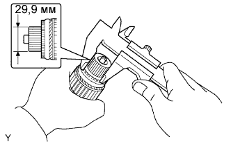
Using vernier calipers, measure the commutator diameter.
- Standard diameter:
- 29.9 mm (1.1772 in.)
- Minimum diameter:
- 28.8 mm (1.1339 in.)
 |
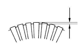
Using vernier calipers, measure the undercut depth of the commutator.
- Standard depth:
- 0.9 mm (0.0354 in.)
- Minimum depth:
- 0.4 mm (0.0157 in.)
 |
| 3. INSPECT STARTER BRUSH HOLDER ASSEMBLY |
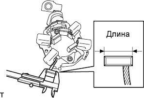
Using vernier calipers, measure the brush length.
- Standard length:
- 10.5 mm (0.4134 in.)
- Minimum length:
- 7.0 mm (0.2756 in.)
 |
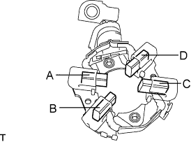
Check the brush holder.
Using an ohmmeter, measure the resistance between the brushes.
- Standard resistance:
Tester Connection Specified Condition A - B 10 kΩ or higher A - C 10 kΩ or higher A - D Below 1 Ω B - C Below 1 Ω B - D 10 kΩ or higher C - D 10 kΩ or higher
 |
| 4. INSPECT STARTER CLUTCH SUB-ASSEMBLY |
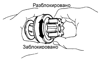
Check the starter clutch pinion gear.
Hold the starter clutch and rotate the pinion gear clockwise, and check that it turns freely. Try to rotate the pinion gear counterclockwise and check that it locks.
If necessary, replace the starter clutch sub-assembly.
 |
| 5. INSPECT MAGNET STARTER SWITCH ASSEMBLY |
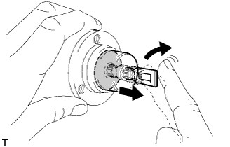
Check the plunger.
Install the plunger and spring onto the switch body.
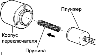 |
Push in the plunger and check that it returns quickly to its original position.
If necessary, replace the magnet starter switch assembly.
 |
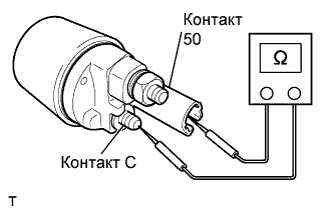
Check the pull-in coil for an open circuit.
Using an ohmmeter, measure the resistance between terminals 50 and C.
- Standard resistance:
- Below 1 Ω
 |
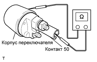
Check whether the holding coil has an open circuit.
Using an ohmmeter, measure the resistance between terminal 50 and the switch body.
- Standard resistance:
- Below 1.5 Ω
 |