READ VALUE USING INTELLIGENT TESTER (ACCELERATOR POSITION NO. 1 AND ACCELERATOR POSITION NO. 2)
INSPECT ECM (VCPA AND VCP2 VOLTAGE)
INSPECT ECM (ACCELERATOR PEDAL POSITION CONTROL CIRCUIT)
CHECK HARNESS AND CONNECTOR (ACCELERATOR PEDAL POSITION SENSOR - ECM)
CHECK HARNESS AND CONNECTOR (ACCELERATOR PEDAL POSITION SENSOR - ECM)
DTC P2120 Throttle / Pedal Position Sensor / Switch "D" Circuit |
DTC P2122 Throttle / Pedal Position Sensor / Switch "D" Circuit Low Input |
DTC P2123 Throttle / Pedal Position Sensor / Switch "D" Circuit High Input |
DTC P2125 Throttle / Pedal Position Sensor / Switch "E" Circuit |
DTC P2127 Throttle / Pedal Position Sensor / Switch "E" Circuit Low Input |
DTC P2128 Throttle / Pedal Position Sensor / Switch "E" Circuit High Input |
DTC P2138 Throttle / Pedal Position Sensor / Switch "D" / "E" Voltage Correlation |
- УКАЗАНИЕ:
- These DTCs relate to the accelerator pedal position sensor.
- This electronic throttle control system does not use a throttle cable.
DESCRIPTION
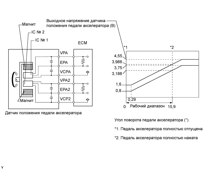
The accelerator pedal position sensor is mounted on the accelerator pedal bracket and has 2 sensor circuits: VPA (main) and VPA2 (sub). This sensor is a non-contact type. It uses Hall-effect elements in order to yield accurate signals, even in extreme driving conditions, such as at high speeds as well as very low speeds. The voltage, which is applied to terminals VPA and VPA2 of the ECM, varies between 0 V and 5 V in proportion to the operating angle of the accelerator pedal (throttle valve). A signal from VPA indicates the actual accelerator pedal opening angle (throttle valve opening angle) and is used for engine control. A signal from VPA2 conveys the status of the VPA circuit and is used to check the accelerator pedal position sensor itself.The ECM monitors the actual accelerator pedal opening angle (throttle valve opening angle) through the signals from VPA and VPA2, and controls the throttle actuator according to these signals.
| DTC No. | DTC Detection Condition | Trouble Area |
| P2120 | VPA fluctuates rapidly beyond upper and lower malfunction thresholds for 0.5 seconds or more (1-trip detection logic) |
|
| P2122 | VPA is 0.4 V or less for 0.5 seconds or more when accelerator pedal is fully released (1-trip detection logic) |
|
| P2123 | VPA is 4.8 V or more for 2.0 seconds or more (1-trip detection logic) |
|
| P2125 | VPA2 fluctuates rapidly beyond upper and lower malfunction thresholds for 0.5 seconds or more (1-trip detection logic) |
|
| P2127 | VPA2 is 1.2 V or less for 0.5 seconds or more when accelerator pedal is fully released (1-trip detection logic) |
|
| P2128 | Conditions (a) and (b) continue for 2.0 seconds or more (1-trip detection logic): (a) VPA2 4.8 V or more (b) VPA between 0.4 V and 3.45 V |
|
| P2138 | Condition (a) or (b) continues for 2.0 seconds or more (1-trip detection logic): (a) Difference between VPA and VPA2 is 0.02 V or less (b) VPA is 0.4 V or less and VPA2 is 1.2 V or less |
|
- УКАЗАНИЕ:
- When any of these DTCs are set, check the accelerator pedal position sensor voltage by selecting the following menu items on the intelligent tester: Powertrain / Engine and ECT / Data List / Accelerator Position No. 1 and Accelerator Position No. 2.
| Trouble Area | Accelerator Position No. 1 When AP Released | Accelerator Position No. 2 When AP Released | Accelerator Position No. 1 When AP Depressed | Accelerator Position No. 2 When AP Depressed |
| VCP circuit open | 0 to 0.2 V | 0 to 0.2 V | 0 to 0.2 V | 0 to 0.2 V |
| Open or ground short in VPA circuit | 0 to 0.2 V | 1.2 to 2.0 V | 0 to 0.2 V | 3.4 to 5.0 V |
| Open or ground short in VPA2 circuit | 0.5 to 1.1 V | 0 to 0.2 V | 2.6 to 4.5 V | 0 to 0.2 V |
| EPA circuit open | 4.5 to 5.0 V | 4.5 to 5.0 V | 4.5 to 5.0 V | 4.5 to 5.0 V |
| Normal condition | 0.5 to 1.1 V | 1.2 to 2.0 V | 2.6 to 4.5 V | 3.4 to 5.0 V |
- УКАЗАНИЕ:
- Accelerator pedal positions are expressed as voltages.
- AP denotes Accelerator Pedal.
FAIL-SAFE
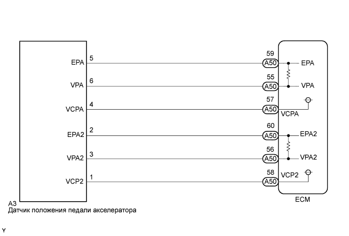
When any of DTCs P2120, P2121, P2122, P2123, P2125, P2127, P2128 and P2138 are set, the ECM enters fail-safe mode. If either of the 2 sensor circuits malfunctions, the ECM uses the remaining circuit to calculate the accelerator pedal position to allow the vehicle to continue driving. If both of the circuits malfunction, the ECM regards the accelerator pedal as being released. As a result, the throttle valve is closed and the engine idles. Fail-safe mode continues until a pass condition is detected, and the ignition switch is turned off.WIRING DIAGRAM
INSPECTION PROCEDURE
- УКАЗАНИЕ:
- Read freeze frame data using the intelligent tester. The ECM records vehicle and driving condition information as freeze frame data the moment a DTC is stored. When troubleshooting, freeze frame data can help determine if the vehicle was moving or stationary, if the engine was warmed up or not, if the air fuel ratio was lean or rich, and other data from the time the malfunction occurred.
| 1.READ VALUE USING INTELLIGENT TESTER (ACCELERATOR POSITION NO. 1 AND ACCELERATOR POSITION NO. 2) |
Connect the intelligent tester to the DLC3.
 |
Turn the ignition switch on (IG) and turn the tester on.
Select the following menu items: Powertrain / Engine and ECT / Data List / Accelerator Position No. 1 and Accelerator Position No. 2.
Read the value displayed on the tester.
- Standard voltage:
Accelerator Pedal Operation Accelerator Position No. 1 Accelerator Position No. 2 Released 0.5 to 1.1 V 1.2 to 2.0 V Depressed 2.6 to 4.5 V 3.4 to 5.0 V
|
| ||||
| OK | ||
| ||
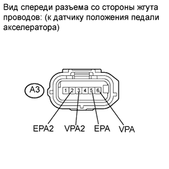
| 2.INSPECT ECM (VCPA AND VCP2 VOLTAGE) |
Disconnect the accelerator pedal position sensor connector.
 |
Turn the ignition switch on (IG).
Measure the voltage according to the value(s) in the table below.
- Standard voltage:
Tester Connection Switch Condition Specified Condition A3-4 (VCPA) - A3-5 (EPA) Ignition switch on (IG) 4.5 to 5.5 V A3-1 (VCP2) - A3-2 (EPA2) Ignition switch on (IG) 4.5 to 5.5 V
Reconnect the accelerator pedal position sensor connector.
|
| ||||
| OK | |
| 3.INSPECT ECM (ACCELERATOR PEDAL POSITION CONTROL CIRCUIT) |
Disconnect accelerator pedal position sensor connector.
 |
Measure the resistance according to the value(s) in the table below.
- Standard resistance:
Tester Connection Condition Specified Value A3-2 (EPA2) - A3-3 (VPA2) Always 36.60 to 41.61 kΩ A3-5 (EPA) - A3-6 (VPA) Always 36.60 to 41.61 kΩ
|
| ||||
| OK | ||
| ||
| 4.CHECK HARNESS AND CONNECTOR (ACCELERATOR PEDAL POSITION SENSOR - ECM) |
Disconnect the accelerator pedal position sensor connector.
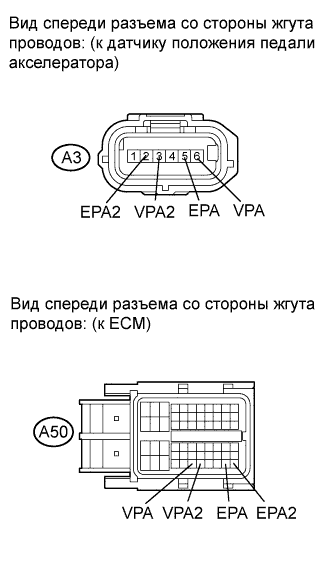 |
Disconnect the ECM connector.
Measure the resistance according to the value(s) in the table below.
- Standard resistance (Check for open):
Tester Connection Condition Specified Condition A3-6 (VPA) - A50-55 (VPA) Always Below 1 Ω A3-5 (EPA) - A50-59 (EPA) Always Below 1 Ω A3-3 (VPA2) - A50-56 (VPA2) Always Below 1 Ω A3-2 (EPA2) - A50-60 (EPA2) Always Below 1 Ω
- Standard resistance (Check for short):
Tester Connection Condition Specified Condition A3-6 (VPA) or A50-55 (VPA) - Body ground Always 10 kΩ or higher A3-5 (EPA) or A50-59 (EPA) - Body ground Always 10 kΩ or higher A3-3 (VPA2) or A50-56 (VPA2) - Body ground Always 10 kΩ or higher A3-2 (EPA2) or A50-60 (EPA2) - Body ground Always 10 kΩ or higher
Reconnect the accelerator pedal position sensor connector.
Reconnect the ECM connector.
|
| ||||
| OK | ||
| ||
| 5.CHECK HARNESS AND CONNECTOR (ACCELERATOR PEDAL POSITION SENSOR - ECM) |
Disconnect the accelerator pedal position sensor connector.
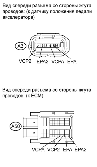 |
Disconnect the ECM connector.
Measure the resistance according to the value(s) in the table below.
- Standard resistance (Check for open):
Tester Connection Condition Specified Condition A3-5 (EPA) - A50-59 (EPA) Always Below 1 Ω A3-4 (VCPA) - A50-57 (VCPA) Always Below 1 Ω A3-2 (EPA2) - A50-60 (EPA2) Always Below 1 Ω A3-1 (VCP2) - A50-58 (VCP2) Always Below 1 Ω
- Standard resistance (Check for short):
Tester Connection Condition Specified Condition A3-5 (EPA) or A50-59 (EPA) - Body ground Always 10 kΩ or higher A3-4 (VCPA) or A50-57 (VCPA) - Body ground Always 10 kΩ or higher A3-2 (EPA2) or A50-60 (EPA2) - Body ground Always 10 kΩ or higher A3-1 (VCP2) or A50-58 (VCP2) - Body ground Always 10 kΩ or higher
Reconnect the accelerator pedal position sensor connector.
Reconnect the ECM connector.
|
| ||||
| OK | ||
| ||