Dtc P0037 Oxygen Sensor Heater Control Circuit Low (Bank 1 Sensor 2). Corolla Auris
Двигатель. COROLLA, AURIS. ZZE150 ZRE151,152 NDE150
DESCRIPTION
WIRING DIAGRAM
INSPECTION PROCEDURE
INSPECT HEATED OXYGEN SENSOR (HEATER RESISTANCE)
CHECK HEATED OXYGEN SENSOR (POWER SOURCE)
CHECK HARNESS AND CONNECTOR (HEATED OXYGEN SENSOR - ECM)
INSPECT FUSE (EFI NO. 2 FUSE)
DTC P0037 Oxygen Sensor Heater Control Circuit Low (Bank 1 Sensor 2) |
DTC P0038 Oxygen Sensor Heater Control Circuit High (Bank 1 Sensor 2) |
DESCRIPTION
- Refer to DTC P0136 (See page Нажмите здесь).
- УКАЗАНИЕ:
- Sensor 2 refers to the sensor mounted behind the three way catalytic converter and located far from the engine assembly.
- When any of these DTCs are set, the ECM enters fail-safe mode. The ECM turns off the heated oxygen sensor heater in fail-safe mode. Fail-safe mode continues until the ignition switch is turned off.
DTC No.
| DTC Detection Condition
| Trouble Area
|
P0037
| Heated oxygen sensor heater current is below 0.3 A when heater operates with +B greater than 11.5 V
(1-trip detection logic)
| - Open in heated oxygen sensor heater circuit
- Heated oxygen sensor heater (sensor 2)
- Integration relay (EFI MAIN relay)
- ECM
|
P0038
| Heated oxygen sensor heater current exceeds 2 A when heater operates
(1-trip detection logic)
| - Short in heated oxygen sensor heater circuit
- Heated oxygen sensor heater (sensor 2)
- Integration relay (EFI MAIN relay)
- ECM
|
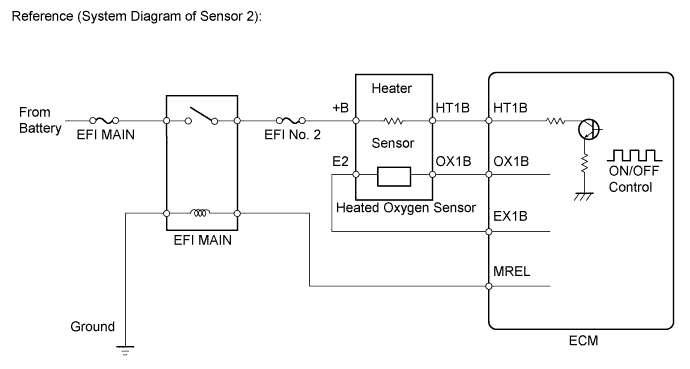
WIRING DIAGRAM
Refer to DTC P2195 (See page Нажмите здесь).
INSPECTION PROCEDURE
- УКАЗАНИЕ:
- Read freeze frame data using the intelligent tester. The ECM records vehicle and driving condition information as freeze frame data the moment a DTC is stored. When troubleshooting, freeze frame data can help determine if the vehicle was moving or stationary, if the engine was warmed up or not, if the air fuel ratio was lean or rich, and other data from the time the malfunction occurred.
| 1.INSPECT HEATED OXYGEN SENSOR (HEATER RESISTANCE) |
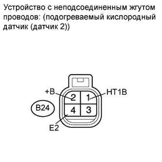
Disconnect the heated oxygen sensor connector.
Measure the resistance according to the value(s) in the table below.
- Standard resistance:
Tester Connection
| Condition
| Specified Condition
|
B24-1 (HT1B) - B24-2 (+B)
| 20°C (68°F)
| 11 to 16 Ω
|
B24-1 (HT1B) - B24-4 (E2)
| Always
| 10 kΩ or higher
|
Reconnect the heated oxygen sensor connector.
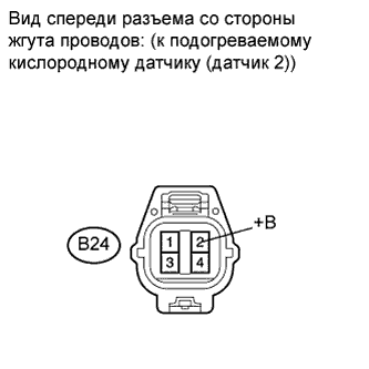
| 2.CHECK HEATED OXYGEN SENSOR (POWER SOURCE) |
Disconnect the heated oxygen sensor connector.
Turn the ignition switch on (IG).
Measure the voltage according to the value(s) in the table below.
- Standard voltage:
Tester Connection
| Switch Condition
| Specified Condition
|
B24-2 (+B) - Body ground
| Ignition switch on (IG)
| 9 to 14 V
|
Reconnect the heated oxygen sensor connector.
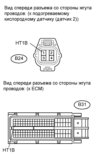
| 3.CHECK HARNESS AND CONNECTOR (HEATED OXYGEN SENSOR - ECM) |
Disconnect the heated oxygen sensor connector.
Disconnect the ECM connector.
Measure the resistance according to the value(s) in the table below.
- Standard resistance (Check for open):
Tester Connection
| Condition
| Specified Condition
|
B24-1 (HT1B) - B31-47 (HT1B)
| Always
| Below 1 Ω
|
- Standard resistance (Check for short):
Tester Connection
| Condition
| Specified Condition
|
B24-1 (HT1B) or B31-47 (HT1B) - Body ground
| Always
| 10 kΩ or higher
|
Reconnect the heated oxygen sensor connector.
Reconnect the ECM connector.
| | REPAIR OR REPLACE HARNESS OR CONNECTOR (HEATED OXYGEN SENSOR - ECM) |
|
|
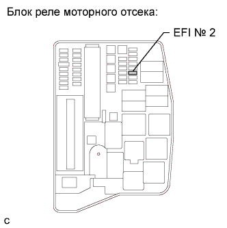
| 4.INSPECT FUSE (EFI NO. 2 FUSE) |
Remove the EFI No. 2 fuse from the engine room relay block.
Measure the resistance according to the value(s) in the table below.
- Standard resistance:
Tester Connection
| Condition
| Specified Condition
|
EFI No. 2 fuse
| Always
| Below 1 Ω
|
Reinstall the EFI No. 2 fuse.
| | REPLACE FUSE (EFI NO. 2 FUSE) |
|
|
| OK |
|
|
|
| REPAIR OR REPLACE HARNESS OR CONNECTOR (HEATED OXYGEN SENSOR - INTEGRATION RELAY (EFI MAIN RELAY)) |
|