Terminal No. (Symbols)
| Wiring Colors
| Terminal Descriptions
| Conditions
| Specified Conditions
|
A50-20 (BATT) - B31-104 (E1)
| P - BR
| Battery (for measuring battery voltage and for ECM memory)
| Always
| 9 to 14 V
|
A50-2 (+B) - B31-104 (E1)
| B - BR
| Power source of ECM
| Ignition switch on (IG)
| 9 to 14 V
|
A50-1 (+B2) - B31-104 (E1)
| B - BR
| Power source of ECM
| Ignition switch on (IG)
| 9 to 14 V
|
A50-3 (+BM) - B31-104 (E1)
| B - BR
| Power source of throttle actuator
| Always
| 9 to 14 V
|
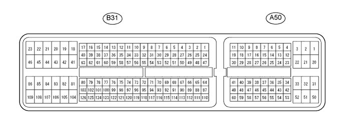
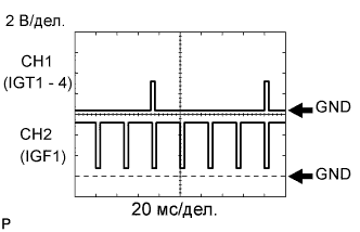
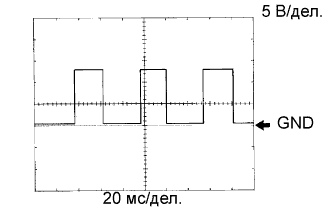
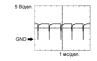
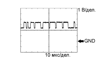
B31-85 (IGT1) - B31-104 (E1)
| W-L - BR
| Ignition coil
(ignition signal)
| Idling
| Pulse generation
(see waveform 1)
|
B31-84 (IGT2) - B31-104 (E1)
| B - BR
|
B31-83 (IGT3) - B31-104 (E1)
| L-B - BR
|
B31-82 (IGT4) - B31-104 (E1)
| B - BR
|
B31-81 (IGF1) - B31-104 (E1)
| Y - BR
| Ignition coil
(ignition confirmation signal)
| Ignition switch on (IG)
| 4.5 to 5.5 V
|
Idling
| Pulse generation
(see waveform 1)
|
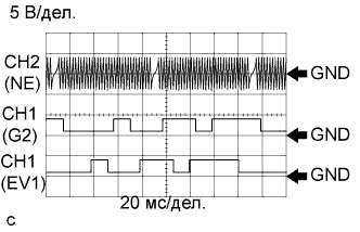
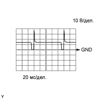
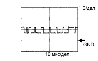
B31-122 (NE+) - B31-121 (NE-)
| R - G
| Crankshaft position sensor
| Idling with warm engine
| Pulse generation
(see waveform 2)
|
B31-99 (G2+) - B31-98 (G2-)
| R - W
| Variable valve timing (VVT) sensor (Intake side)
| Idling with warm engine
| Pulse generation
(see waveform 2)
|
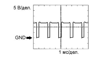
B31-108 (#10) - B31-45 (E01)
| V - BR
| Injector
| Ignition switch on (IG)
| 9 to 14 V
|
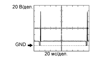
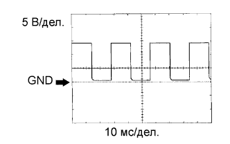
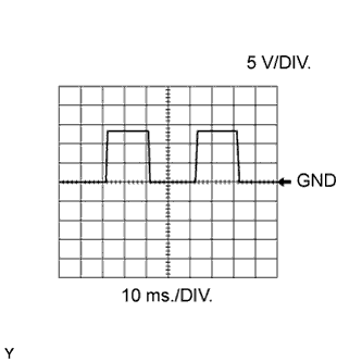
B31-107 (#20) - B31-45 (E01)
| Y - BR
| Idling
| Pulse generation
(see waveform 3)
|
B31-106 (#30) - B31-45 (E01)
| G - BR
|
B31-105 (#40) - B31-45 (E01)
| LG - BR
|
B31-109 (HA1A) - B31-46 (E04)
| R - W-B
| Air fuel ratio sensor heater (sensor 1)
| Ignition switch on (IG)
| 9 to 14 V
|
Idling
| Pulse generation
(see waveform 15)
|
B31-112 (A1A+) - B31-104 (E1)
| Y - BR
| Air fuel ratio sensor (sensor 1)
| Ignition switch on (IG)
| 3.0 V*3
|
B31-113 (A1A-) - B31-104 (E1)
| L - BR
| Air fuel ratio sensor (sensor 1)
| Ignition switch on (IG)
| 3.3 V*3
|
B31-47 (HT1B) - B31-86 (E03)
| P - W-B
| Heated oxygen sensor heater (sensor 2)
| Ignition switch on (IG)
| 9 to 14 V
|
Idling
| Below 3.0 V
|
B31-64 (OX1B) - B31-87 (EX1B)
| B - LG-B
| Heated oxygen sensor (sensor 2)
| Engine speed maintained at 2500 rpm for 2 minutes after warming up sensor
| Pulse generation
(see waveform 4)
|
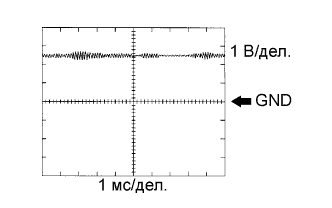
B31-110 (KNK1) - B31-111 (EKNK)
| B - W
| Knock sensor
| Engine speed maintained at 4000 after warming up engine
| Pulse generation
(see waveform 5)
|
A50-8 (SPD) - B31-104 (E1)
| V - BR
| Speed signal from combination meter
| Driving at 20 km/h (12 mph)
| Pulse generation
(see waveform 6)
|
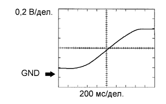
B31-97 (THW) - B31-96 (ETHW)
| B - BR
| Engine coolant temperature sensor
| Idling, Engine coolant temperature 80°C (176°F)
| 0.2 to 1.0 V
|
B31-65 (THA) - B31-88 (ETHA)
| P - BR-W
| Intake air temperature sensor
| Idling, Intake air temperature 20°C (68°F)
| 0.5 to 3.4 V
|
B31-118 (VG) - B31-116 (E2G)
| V - B
| Mass air flow meter
| Idling, Shift lever position P or N, air conditioner OFF
| 0.5 to 3.0 V
|
A50-24 (W) - B31-104 (E1)
| R - BR
| MIL
| Ignition switch on (IG) (MIL goes off)
| Below 3.0 V
|
Idling
| 9 to 14 V
|
A50-48 (STA) - B31-104 (E1)
| LG - BR
| Starter signal
| Cranking
| 5.5 V or more
|
A50-13 (ACCR) (*1) - B31-104 (E1)
| L-Y - BR
| ACC relay control signal
| Cranking
| Below 1.5 V
|
A50-14 (STSW) (*1) - B31-104 (E1)
| W-G - BR
| Starter relay operation signal
| Cranking
| 9 to 14 V
|
B31-115 (VTA1) - B31-91 (ETA)
| LG - BR
| Throttle position sensor (for engine control)
| Ignition switch on (IG), Throttle valve fully closed
| 0.5 to 1.2 V
|
Ignition switch on (IG), Throttle valve fully open
| 3.2 to 4.8 V
|
B31-114 (VTA2) - B31-91 (ETA)
| R-G - BR
| Throttle position sensor (for sensor malfunction detection)
| Ignition switch on (IG), Accelerator pedal released
| 2.1 to 3.1 V
|
Ignition switch on (IG), Accelerator pedal depressed
| 4.5 to 5.5 V
|
B31-67 (VCTA) - B31-91 (ETA)
| Y - BR
| Power source of sensor (specific voltage)
| Ignition switch on (IG)
| 4.5 to 5.5 V
|
A50-57 (VCPA) - A50-59 (EPA)
| P - R
| Power source of accelerator pedal position sensor (for VPA)
| Ignition switch on (IG)
| 4.5 to 5.5 V
|
A50-55 (VPA) - A50-59 (EPA)
| L - R
| Accelerator pedal position sensor (for engine control)
| Ignition switch on (IG), Accelerator pedal released
| 0.5 to 1.1 V
|
Ignition switch on (IG), Accelerator pedal fully depressed
| 2.6 to 4.5 V
|
A50-56 (VPA2) - A50-60 (EPA2)
| Y - O
| Accelerator pedal position sensor (for sensor malfunctioning detection)
| Ignition switch on (IG), Accelerator pedal released
| 1.2 to 2.0 V
|
Ignition switch on (IG), Accelerator pedal fully depressed
| 3.4 to 5.0 V
|
A50-58 (VCP2) - A50-60 (EPA2)
| B - O
| Power source of accelerator pedal position sensor (for VPA2)
| Ignition switch on (IG)
| 4.5 to 5.0 V
|
B31-42 (M+) - B31-43 (ME01)
| P - W-B
| Throttle actuator
| Idling with warm engine
| Pulse generation
(see waveform 7)
|
B31-41 (M-) - B31-43 (ME01)
| L - W-B
| Throttle actuator
| Idling with warm engine
| Pulse generation
(see waveform 8)
|
A50-36 (STP) - B31-104 (E1)
| L - BR
| Stop light switch
| Brake pedal depressed
| 9 to 14 V
|
Brake pedal released
| Below 1.5 V
|
A50-35 (ST1-) - B31-104 (E1)
| R - BR
| Stop light switch
| Ignition switch on (IG), Brake pedal depressed
| Below 1.5 V
|
Ignition switch on (IG), Brake pedal released
| 9 to 14 V
|
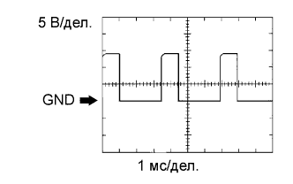
B31-49 (PRG) - B31-104 (E1)
| L-B - BR
| Purge VSV
| Ignition switch on (IG)
| 9 to 14 V
|
Idling
| Pulse generation
(see waveform 9)
|
A50-7 (FC) - B31-104 (E1)
| O - BR
| Fuel pump control
| Ignition switch on (IG)
| 9 to 14 V
|
Idling
| Below 1.5 V
|
A50-15 (TACH) - B31-104 (E1)
| GR - BR
| Engine speed
| Idling
| Pulse generation
(see waveform 10)
|
A50-27 (TC) - B31-104 (E1)
| P - BR
| Terminal TC of DLC3
| Ignition switch on (IG)
| 9 to 14 V
|
B31-100 (OC1+) - B31-123 (OC1-)
| B - V-Y
| Camshaft timing oil control valve (Intake side)
| Idling
| Pulse generation
(see waveform 11)
|
A50-41 (CANH) - B31-104 (E1)
| Y - BR
| CAN communication line
| Ignition switch on (IG)
| Pulse generation
(see waveform 12)
|
A50-49 (CANL) - B31-104 (E1)
| W - BR
| CAN communication line
| Ignition switch on (IG)
| Pulse generation
(see waveform 13)
|
A50-28 (IGSW) - B31-104 (E1)
| B - BR
| Ignition switch
| Ignition switch on (IG)
| 9 to 14 V
|
A50-44 (MREL) - B31-104 (E1)
| L - BR
| EFI MAIN relay
| Ignition switch on (IG)
| 9 to 14 V
|
B31-60 (OE1+) - B31-61 (OE1-)
| BR-P
| Camshaft timing oil control valve (Exhaust side)
| Idling
| Pulse generation
(see wave form 14)
|
B31-76 (EV1+) - B31-75 (EV1-)
| R - W
| Variable valve timing (VVT) sensor (Exhaust side)
| Idling with warm engine
| Pulse generation
(see wave form 2)
|
B31-70 (VCV1) - B31-104 (E1)
| BR-R - BR
| Power source for VVT sensor (specific voltage)
| Ignition switch on (IG)
| 4.5 to 5.5 V
|
B31-117 (VC) - B31-104 (E1)
| BR-R - BR
| Power source for VVT sensor (specific voltage)
| Ignition switch on (IG)
| 4.5 to 5.5 V
|
B31-52 (STAR) - B31-104 (E1)
| W - BR
| Starter relay control
| Ignition switch on (IG)
| Below 1.5 V
|
Cranking
| 5.5 V or more
|
A50-43 (RFC) - B31-104 (E1)
| R-G - BR
| Cooling fan control
| Ignition switch on (IG)
| 4.5 to 5.5 V
|