Масляный Насос Снятие. Corolla Auris
Двигатель. COROLLA, AURIS. ZZE150 ZRE151,152 NDE150
REMOVE ENGINE WITH TRANSAXLE
INSTALL ENGINE TO ENGINE STAND
REMOVE GENERATOR ASSEMBLY
REMOVE CRANKSHAFT POSITION SENSOR
REMOVE NO. 2 IDLER PULLEY SUB-ASSEMBLY
REMOVE NO. 1 IDLER PULLEY SUB-ASSEMBLY
REMOVE NO. 4 WATER BY-PASS PIPE
REMOVE ENGINE MOUNTING BRACKET
REMOVE V-RIBBED BELT TENSIONER ASSEMBLY
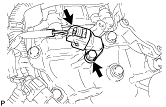
REMOVE VACUUM PUMP ASSEMBLY
REMOVE CAMSHAFT POSITION SENSOR
REMOVE INJECTION PIPE SUB-ASSEMBLY
REMOVE NO. 2 NOZZLE LEAKAGE PIPE
REMOVE FUEL HOSE PROTECTOR
REMOVE FUEL TUBE SUB-ASSEMBLY
REMOVE OIL FILLER CAP SUB-ASSEMBLY
REMOVE NO. 1 NOZZLE LEAKAGE PIPE ASSEMBLY
REMOVE NO. 1 NOZZLE HOLDER CLAMP
REMOVE INJECTOR ASSEMBLY
REMOVE CYLINDER HEAD COVER SUB-ASSEMBLY
REMOVE ENGINE OIL LEVEL SENSOR
REMOVE OIL LEVEL GAUGE GUIDE
REMOVE ENGINE COVER BRACKET
REMOVE COMMON RAIL ASSEMBLY
REMOVE DIESEL THROTTLE BODY ASSEMBLY
REMOVE OIL FILTER CAP ASSEMBLY
REMOVE OIL FILTER ELEMENT
REMOVE NO. 2 OIL PAN SUB-ASSEMBLY
REMOVE OIL FILTER BRACKET
REMOVE OIL STRAINER SUB-ASSEMBLY
REMOVE CRANKSHAFT PULLEY
REMOVE WATER PUMP ASSEMBLY
REMOVE NO. 1 WATER BY-PASS HOSE
REMOVE OIL COOLER ASSEMBLY
REMOVE NO. 3 WATER BY-PASS PIPE
REMOVE NO. 1 TURBO OIL PIPE
REMOVE NO. 1 OIL COOLER BRACKET
REMOVE NO. 2 WATER BY-PASS PIPE
REMOVE NO. 4 WATER BY-PASS HOSE
REMOVE WATER INLET HOUSING
REMOVE TIMING CHAIN COVER SUB-ASSEMBLY
| 1. REMOVE ENGINE WITH TRANSAXLE |
See page Нажмите здесь
| 2. INSTALL ENGINE TO ENGINE STAND |
Set the engine on an engine stand and remove the sling device and chain block from the engine.
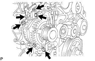
| 3. REMOVE GENERATOR ASSEMBLY |
Disconnect the generator connector.
Remove the terminal cap.
Remove the nut and bolt, and disconnect the generator wire from terminal B.
Remove the 3 bolts and generator assembly.
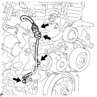
| 4. REMOVE CRANKSHAFT POSITION SENSOR |
Disconnect the sensor connector.
Disconnect the sensor connector from the bracket.
Disconnect the sensor wire harness clamp.
Remove the bolt and sensor.
| 5. REMOVE NO. 2 IDLER PULLEY SUB-ASSEMBLY |
Remove the bolt, plate and idler pulley.
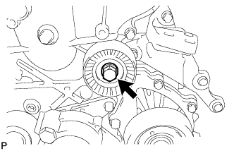
| 6. REMOVE NO. 1 IDLER PULLEY SUB-ASSEMBLY |
Using a screwdriver, remove the idler pulley cover plate.
Remove the bolt and idler pulley.
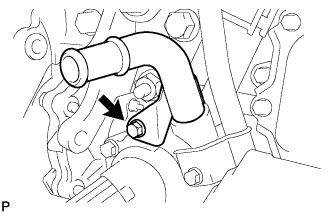
| 7. REMOVE NO. 4 WATER BY-PASS PIPE |
Remove the bolt and No. 4 water by-pass pipe.
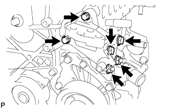
| 8. REMOVE ENGINE MOUNTING BRACKET |
Remove the 4 bolts, 2 nuts and engine mounting bracket.
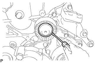
| 9. REMOVE V-RIBBED BELT TENSIONER ASSEMBLY |
Remove the 3 bolts and tensioner.
- ПРИМЕЧАНИЕ:
- As the bolts' heads are not as thick as typical bolts, be careful not to damage them during removal.
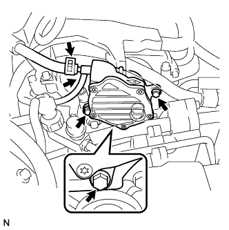
| 10. REMOVE VACUUM PUMP ASSEMBLY |
Сдвиньте фиксатор и отсоедините 2 вакуумных шланга.
Выверните 3 болта и снимите вакуумный насос в сборе.
Снимите 2 кольцевых уплотнения с вакуумного насоса в сборе.
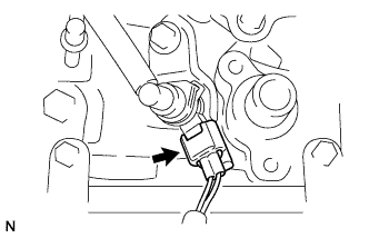
| 11. REMOVE CAMSHAFT POSITION SENSOR |
Disconnect the sensor connector.
Remove the bolt and sensor.
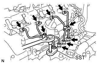
| 12. REMOVE INJECTION PIPE SUB-ASSEMBLY |
- ПРИМЕЧАНИЕ:
- After removing the fuel pipe, cover the common rail with electrical tape to prevent dirt or foreign objects from entering the pipe inlet. Also protect the injector inlets with electrical tape or plastic bags.
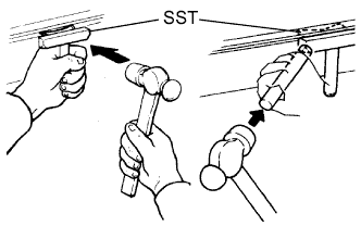
Remove the 2 bolts and 4 injection pipe clamps.
Using SST, loosen the nut at the common rail end of the injection pipe.
- SST
- 09023-38401
Using SST, loosen the nut at the injector end of the injection pipe.
- SST
- 09023-38401
Remove the No. 1 injection pipe sub-assembly.
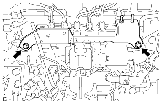
| 13. REMOVE NO. 2 NOZZLE LEAKAGE PIPE |
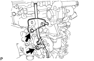
| 14. REMOVE FUEL HOSE PROTECTOR |
Remove the bolt and fuel hose protector.
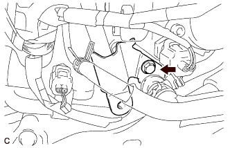
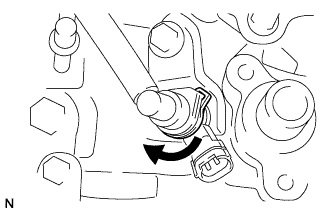
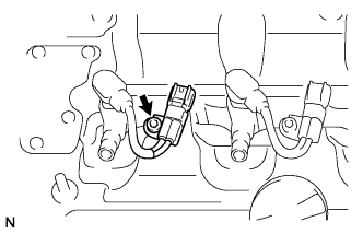
| 15. REMOVE FUEL TUBE SUB-ASSEMBLY |
Disconnect the exhaust fuel addition injector connector.
Turn the retainer as shown in the illustration.
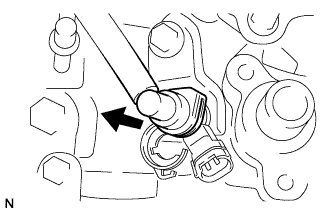
Disconnect the fuel tube sub-assembly.
- ПРИМЕЧАНИЕ:
- Be careful not to bend the fuel tube.
Remove the union bolt, fuel tube sub-assembly and gasket.
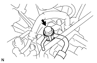
| 16. REMOVE OIL FILLER CAP SUB-ASSEMBLY |
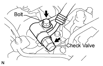
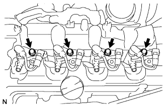
| 17. REMOVE NO. 1 NOZZLE LEAKAGE PIPE ASSEMBLY |
Remove the fuel check valve, bolt and gasket.
Remove the 4 union bolts, 4 gaskets and No. 1 nozzle leakage pipe.
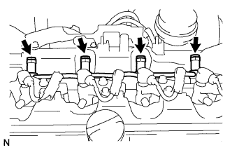
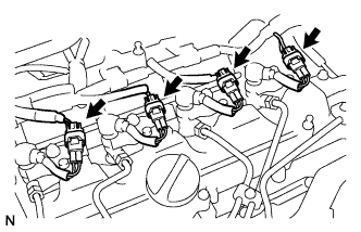
| 18. REMOVE NO. 1 NOZZLE HOLDER CLAMP |
Disconnect the 4 injector connectors.
Using a hexagon socket wrench, remove the 4 bolts.
Remove the 4 bolts, 4 washers, and 4 nozzle holder clamps.
| 19. REMOVE INJECTOR ASSEMBLY |
Remove the 4 injectors and 4 injection nozzle seats from the cylinder head.
Remove the O-rings from each injector.
- ПРИМЕЧАНИЕ:
- When removing the injector assembly, store them in correct order so that they can be returned to the original locations when reassembling.
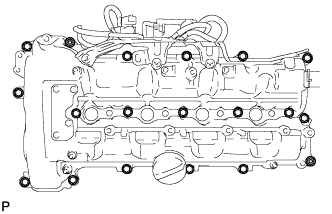
| 20. REMOVE CYLINDER HEAD COVER SUB-ASSEMBLY |
Disconnect the ventilation hose.
Remove the 2 nuts, 2 washers, 13 bolts, 4 nozzle holder clamp seats and cylinder head cover.
Remove the cylinder head cover gasket and No. 2 cylinder head cover gasket.
| 21. REMOVE ENGINE OIL LEVEL SENSOR |
Remove the 4 bolts and level sensor.
| 22. REMOVE OIL LEVEL GAUGE GUIDE |
Remove the 2 bolts and oil dipstick guide.
Remove the O-ring from the dipstick guide.
| 23. REMOVE ENGINE COVER BRACKET |
Remove the bolt and pressure sensor.
Remove the 2 bolts and engine cover bracket.
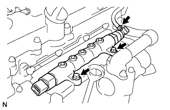
| 24. REMOVE COMMON RAIL ASSEMBLY |
Using pliers, grip the claws of the clip and slide the clip to disconnect the pressure fuel hose.
Remove the 2 bolts, common rail assembly and intake manifold insulator.
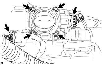
| 25. REMOVE DIESEL THROTTLE BODY ASSEMBLY |
Disconnect the throttle position sensor connector.
Disconnect the throttle motor connector.
Remove the 2 nuts and 2 bolts, and then remove the diesel throttle body and gasket.
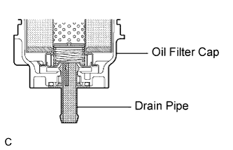
| 26. REMOVE OIL FILTER CAP ASSEMBLY |
Remove the oil filter drain plug and O-ring, then insert the drain pipe into the oil filter cap and drain the engine oil into a container.
- УКАЗАНИЕ:
- The drain pipe is supplied with the oil filter element.
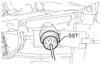
Using SST, remove the oil filter cap.
- SST
- 09228-06501
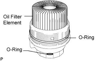
| 27. REMOVE OIL FILTER ELEMENT |
Remove the oil filter element and 2 O-rings from the oil filter cap.
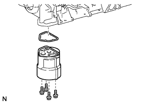
| 28. REMOVE NO. 2 OIL PAN SUB-ASSEMBLY |
Remove the drain plug and gasket.
Remove the 18 bolts and 2 nuts.
Insert the blade of SST between the oil pan and crankshaft bearing cap, cut through the applied sealer, and remove the oil pan.
- SST
- 09032-00100
- ПРИМЕЧАНИЕ:
- Do not use SST for the timing chain cover side.
- Be careful not to damage the contact surfaces of the oil pan.
| 29. REMOVE OIL FILTER BRACKET |
Remove the 4 bolts, oil filter bracket, and gasket.
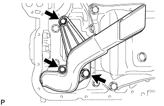
| 30. REMOVE OIL STRAINER SUB-ASSEMBLY |
Remove the 3 bolts, oil strainer, and O-ring.
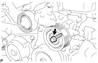
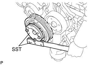
| 31. REMOVE CRANKSHAFT PULLEY |
Align the keyway of the pulley with the key located on the crankshaft, then slide the pulley into place.
Using SST, install the pulley bolt.
- SST
- 09213-58013
09330-00021
- Момент затяжки:
- 250 Н*м{2549 кгс*см, 184 фунт-сила-футов}
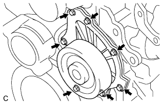
| 32. REMOVE WATER PUMP ASSEMBLY |
Remove the 7 bolts, water pump and gasket.
| 33. REMOVE NO. 1 WATER BY-PASS HOSE |
Loosen the 2 clips and remove the water by-pass hose.
| 34. REMOVE OIL COOLER ASSEMBLY |
Remove the No. 1 cylinder block insulator.
Disconnect the connector from the oil pressure switch.
Remove the 5 bolts, engine oil cooler, and 3 O-rings.
| 35. REMOVE NO. 3 WATER BY-PASS PIPE |
Remove the 2 bolts, O-ring and by-pass pipe.
| 36. REMOVE NO. 1 TURBO OIL PIPE |
Remove the 2 union bolts, 2 gaskets and oil pipe.
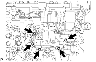
| 37. REMOVE NO. 1 OIL COOLER BRACKET |
Remove the 6 bolts, nut, and oil cooler bracket.
Remove the 3 O-rings.
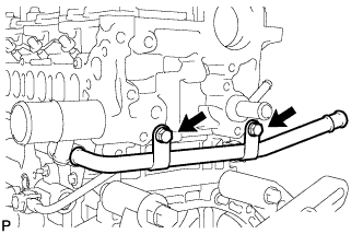
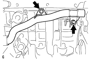
| 38. REMOVE NO. 2 WATER BY-PASS PIPE |
Remove the 2 bolts, O-ring, and by-pass pipe.
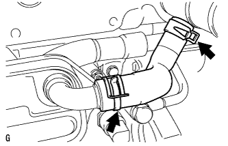
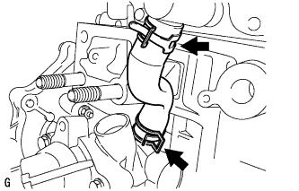
| 39. REMOVE NO. 4 WATER BY-PASS HOSE |
Using needle-nose pliers, grip the claws of the 2 clips, and slide the 2 clips to remove the No. 4 water by-pass hose.
- УКАЗАНИЕ:
- Place a container under the connection before removing the No. 4 water by-pass hose because water in the hose may spill out.
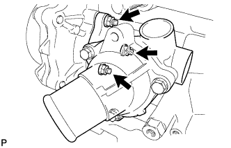
| 40. REMOVE WATER INLET HOUSING |
Remove the 3 nuts, gasket, and inlet housing.
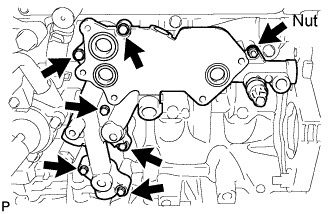
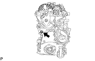
| 41. REMOVE TIMING CHAIN COVER SUB-ASSEMBLY |
Using a 10 mm socket hexagon wrench, remove the timing chain cover tight plug and gasket.
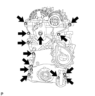
Remove the 13 bolts and seal washer as shown in the illustration.
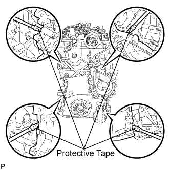
Remove the timing chain cover by prying between the timing chain cover and cylinder head or cylinder block with a screwdriver.
- УКАЗАНИЕ:
- Tape the screwdriver tip before use.
- ПРИМЕЧАНИЕ:
- Do not damage the contact surfaces of the cylinder head, cylinder block, and timing chain cover.
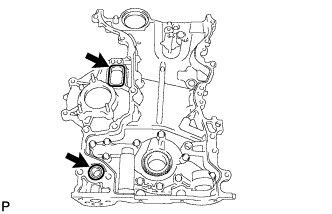
Remove the gasket and O-ring.