Масляный Насос -- Установка |
| 1. INSTALL TIMING CHAIN COVER SUB-ASSEMBLY |
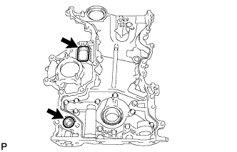
Install a new gasket and O-ring to the timing chain cover as shown in the illustration.
 |
Apply seal packing to the timing chain cover as shown in the illustration.
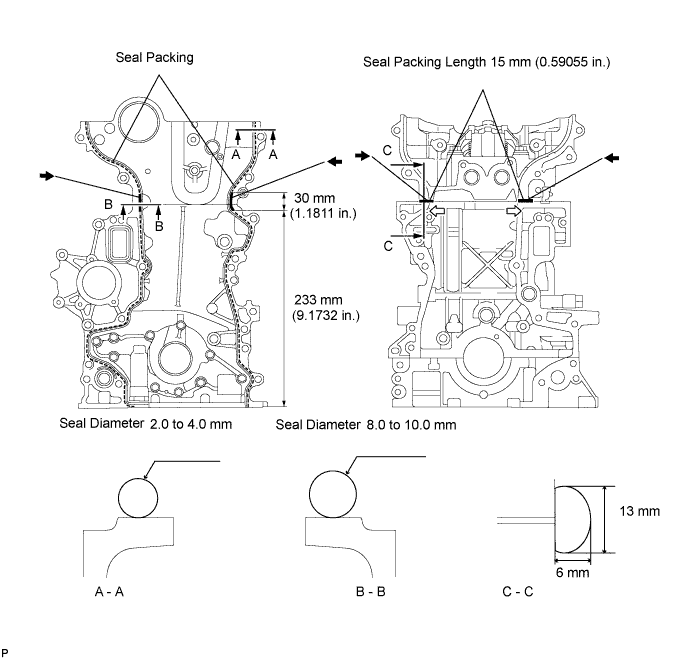
- Seal packing:
- Toyota Genuine Seal Packing Black, Three Bond 1207B or equivalent
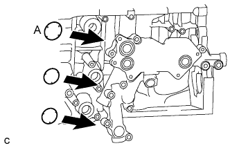
- Standard seal diameter:
Position Specified Condition A - A 2.0 to 4.0 mm (0.079 to 0.157 in.) B - B 8.0 to 10.0 mm (0.315 to 0.394 in.) C - C Width: 13 mm (0.512 in.)
Height: 6 mm (0.236 in.)
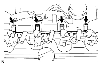
- ПРИМЕЧАНИЕ:
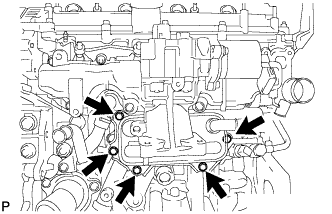
- Be sure to clean and degrease the contact surfaces, especially the 4 areas indicated by the arrows in the illustration.
- When the contact surfaces are wet, wipe them with an oil-free cloth before applying seal packing.
- When applying seal packing to area C - C, apply it in the direction of the white arrows in the illustration.
- Install the crankcase within 3 minutes and tighten the bolts within 15 minutes after applying seal packing.
- Do not start the engine for at least 4 hours after installing.
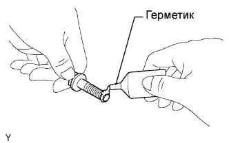
Apply adhesive to the 4 bolts.
- Adhesive:
- Toyota Genuine Adhesive 1324, Three Bond 1324 or equivalent
- УКАЗАНИЕ:
- Bolt length: 37.5 mm (1.476 in.)
 |
Temporarily install the timing chain cover with the 4 bolts.
 |
Temporarily install a new seal washer and bolt A.
- УКАЗАНИЕ:
- Bolt length: 67.5 mm (2.657 in.)
Temporarily install the 8 bolts.
- УКАЗАНИЕ:
- Bolt length: 37.5 mm (1.476 in.)
Using several steps, tighten the 13 bolts.
- Момент затяжки:
- 31.5 Н*м{321 кгс*см, 23 фунт-сила-футов}for except bolt A
- 21 Н*м{214 кгс*см, 15 фунт-сила-футов}for bolt A
Using a 10 mm socket hexagon wrench, install a new gasket and the timing chain cover tight plug.
- Момент затяжки:
- 19 Н*м{194 кгс*см, 14 фунт-сила-футов}
 |
| 2. INSTALL WATER INLET HOUSING |
Install a new gasket and the inlet housing with the 3 nuts.
- Момент затяжки:
- 9.0 Н*м{92 кгс*см, 80 фунт-сила-дюймов}
 |
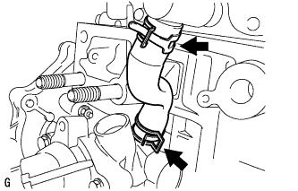
| 3. INSTALL NO. 4 WATER BY-PASS HOSE |
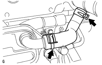
Using needle-nose pliers, grip the claws of the 2 clips and slide the 2 clips to install the No. 4 water by-pass hose.
 |
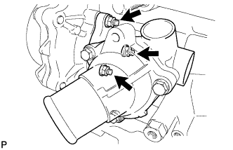
| 4. INSTALL NO. 2 WATER BY-PASS PIPE |
Apply soapy water to a new O-ring and install it to the by-pass pipe.
Install the by-pass pipe to the inlet housing with the 2 bolts.
- Момент затяжки:
- 11 Н*м{112 кгс*см, 8 фунт-сила-футов}
 |
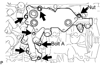
| 5. INSTALL NO. 1 OIL COOLER BRACKET |
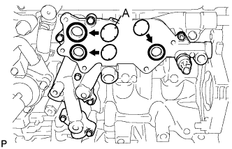
Apply a light coat of engine oil to 2 new O-rings.
- ПРИМЕЧАНИЕ:
- Do not apply engine oil to the new O-ring labeled A.
 |
Install the 3 O-rings to the oil cooler bracket.
Install the oil cooler bracket with the 6 bolts and nut.
- Момент затяжки:
- 11 Н*м{112 кгс*см, 8 фунт-сила-футов}
- УКАЗАНИЕ:
- Bolt length: 36 mm (1.42 in.) for bolt A
- Bolt length: 49 mm (1.93 in.) for except bolt A
 |
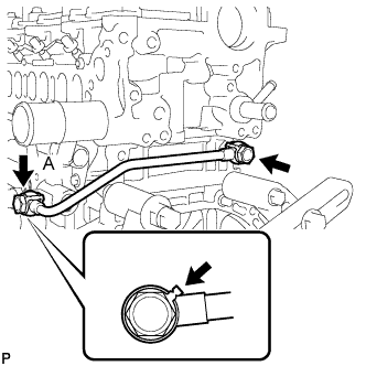
| 6. INSTALL NO. 1 TURBO OIL PIPE |
Install the oil pipe and 2 new gaskets with the 2 union bolts.
- Момент затяжки:
- 35 Н*м{357 кгс*см, 26 фунт-сила-футов}
- УКАЗАНИЕ:
- Be sure to install the union bolt A so that the gasket is positioned as shown in the illustration.
 |
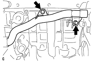
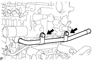
| 7. INSTALL NO. 3 WATER BY-PASS PIPE |
Apply soapy water to a new O-ring and install it to the by-pass pipe.
Install the by-pass pipe with the 2 bolts.
- Момент затяжки:
- 21 Н*м{214 кгс*см, 15 фунт-сила-футов}
 |
| 8. INSTALL OIL COOLER ASSEMBLY |
Apply a light coat of engine oil to 2 new O-rings.
- ПРИМЕЧАНИЕ:
- Do not apply engine oil to the new O-ring labeled A.
 |
Install the 2 O-rings and the new O-ring labeled A to the oil cooler bracket.
Install the oil cooler with the 5 bolts.
- Момент затяжки:
- 11 Н*м{112 кгс*см, 8 фунт-сила-футов}
 |
Connect the oil pressure switch connector.
Install the No. 1 cylinder block insulator.
| 9. INSTALL NO. 1 WATER BY-PASS HOSE |
Install the No. 1 water by-pass hose and tighten the 2 clips.
 |
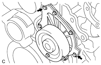
| 10. INSTALL WATER PUMP ASSEMBLY |
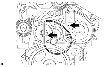
Install a new gasket onto the timing chain cover as shown in the illustration.
 |
Clean the 7 bolts and 7 bolt holes.
Apply adhesive to 2 or 3 threads of the bolt labeled A.
- Adhesive:
- Toyota Genuine Adhesive 1324, Three Bond 1324 or equivalent
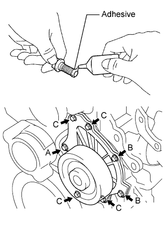 |
Temporarily install the water pump with the 7 bolts.
- Standard bolt length:
Item Specified Condition Bolt A and C 45 mm (1.77 in.) Bolt B 30 mm (1.18 in.)
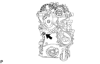
Tighten the 2 bolts indicated by the arrows in the illustration. Then tighten the other bolts.
- Момент затяжки:
- 32 Н*м{326 кгс*см, 24 фунт-сила-футов}
 |
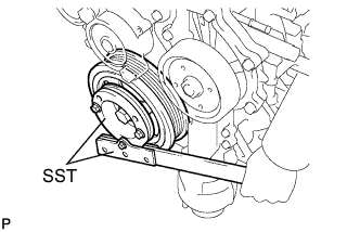
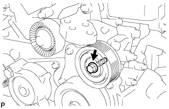
| 11. INSTALL CRANKSHAFT PULLEY |
Align the keyway of the pulley with the key located on the crankshaft, then slide the pulley into place.
Using SST, install the pulley bolt.
- SST
- 09213-58013
09330-00021
- Момент затяжки:
- 250 Н*м{2549 кгс*см, 184 фунт-сила-футов}
 |
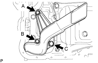
| 12. INSTALL OIL STRAINER SUB-ASSEMBLY |
Install a new O-ring and the oil strainer with the 3 bolts.
- Момент затяжки:
- 9.0 Н*м{92 кгс*см, 80 фунт-сила-дюймов}for bolt A and B
- 42 Н*м{428 кгс*см, 31 фунт-сила-футов}for bolt C
 |
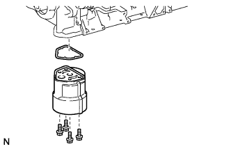
| 13. INSTALL OIL FILTER BRACKET |
Install a new gasket and the oil filter bracket with the 4 bolts.
- Момент затяжки:
- 9.0 Н*м{92 кгс*см, 80 фунт-сила-дюймов}
 |
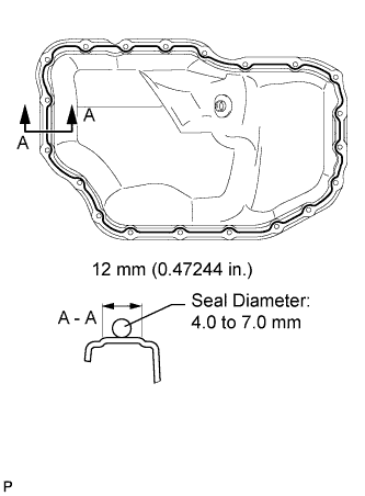
| 14. INSTALL NO. 2 OIL PAN SUB-ASSEMBLY |
Apply seal packing in a continuous bead as shown in the illustration.
- Seal packing:
- Toyota Genuine Seal Packing Black, Three Bond 1207B or equivalent
- Standard seal diameter:
- 4.0 to 7.0 mm (0.157 to 0.276 in.)
- ПРИМЕЧАНИЕ:
- Remove any oil from the contact surfaces.
- Install the oil pan within 3 minutes and tighten the bolts within 10 minutes after applying seal packing.
- Do not start the engine for at least 4 hours after installation.
 |
Install the oil pan with the 18 bolts and 2 nuts.
- Момент затяжки:
- 10.5 Н*м{107 кгс*см, 8 фунт-сила-футов}
 |
Install a new gasket and the drain plug.
- Момент затяжки:
- 38 Н*м{387 кгс*см, 28 фунт-сила-футов}
| 15. INSTALL OIL FILTER ELEMENT |
Clean the inside of oil filter cap, threads, and O-ring groove.
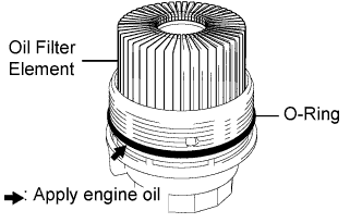 |
Apply a small amount of engine oil to a new O-ring and install it to the oil filter cap assembly.
Install a new oil filter element into the oil filter cap assembly.
Remove any dirt or foreign matter from the contact surfaces of the oil filter cap assembly (with oil filter element) and oil filter bracket.
Install the oil filter cap assembly (with oil filter element) to the oil filter bracket.
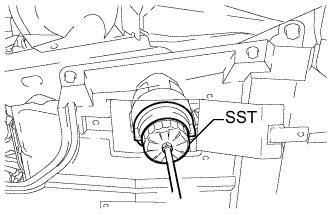
| 16. INSTALL OIL FILTER CAP ASSEMBLY |
Using SST, tighten the oil filter cap.
- SST
- 09228-06501
- Момент затяжки:
- 40 Н*м{408 кгс*см, 30 фунт-сила-футов}
- ПРИМЕЧАНИЕ:
- Check and clean the oil filter installation surface.
 |
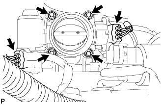
| 17. INSTALL DIESEL THROTTLE BODY ASSEMBLY |
Install a new gasket and the diesel throttle body with the 2 nuts and 2 bolts.
- Момент затяжки:
- 21 Н*м{214 кгс*см, 15 фунт-сила-футов}
 |
Connect the throttle position sensor connector.
Connect the throttle motor connector.
| 18. INSTALL COMMON RAIL ASSEMBLY |
Install the intake manifold insulator and common rail with the 2 bolts.
- Момент затяжки:
- 21 Н*м{210 кгс*см, 15 фунт-сила-футов}
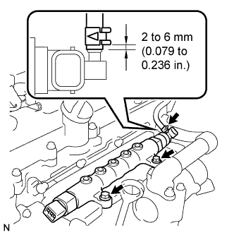 |
Using pliers, grip the claws of the clip and slide the clip to connect the fuel hose as shown in the illustration.
| 19. INSTALL ENGINE COVER BRACKET |
Install the cover bracket with the 2 bolts.
- Момент затяжки:
- 20 Н*м{204 кгс*см, 15 фунт-сила-футов}
 |
Install the pressure sensor with the bolt.
- Момент затяжки:
- 8.8 Н*м{90 кгс*см, 78 фунт-сила-дюймов}
| 20. INSTALL OIL LEVEL GAUGE GUIDE |
Install a new O-ring to the dipstick guide.
Install the dipstick guide with the 2 bolts.
- Момент затяжки:
- 33 Н*м{337 кгс*см, 24 фунт-сила-футов}
 |
| 21. INSTALL ENGINE OIL LEVEL SENSOR |
Install the level sensor with the 4 bolts.
- Момент затяжки:
- 7.0 Н*м{71 кгс*см, 62 фунт-сила-дюймов}
 |
| 22. INSTALL CYLINDER HEAD COVER SUB-ASSEMBLY |
Clean the contact surface of the cylinder head cover, cylinder head and timing chain cover.
Fit a new cylinder head cover gasket and a new No. 2 cylinder head cover gasket into the gasket groove on the cover.
 |
Apply a continuous bead of seal packing (diameter: 8 mm (0.31 in.) to the contact surface between the cylinder head assembly and cylinder head cover assembly as shown in the illustration.
- Seal packing:
- Toyota Genuine Seal Packing Black, Three Bond 1207B or equivalent
- Standard seal diameter:
- 8 mm (0.31 in.)
- ПРИМЕЧАНИЕ:
- Remove any oil from the contact surface.
- Install the cylinder head cover within 3 minutes after applying seal packing.
- Do not apply engine oil for at least 2 hours after installing.
Install the gasket to the cylinder head cover.
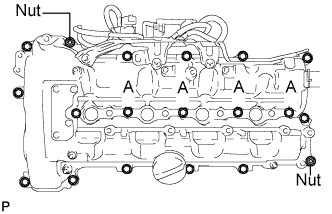
Install the cylinder head cover with the 13 bolts, 4 nozzle holder clamp seats, 2 nuts and 2 washers. Uniformly tighten the bolts and nuts in several passes.
- Момент затяжки:
- 16 Н*м{163 кгс*см, 12 фунт-сила-футов}for bolt A (Nozzle holder clamp seat)
- 11 Н*м{112 кгс*см, 8 фунт-сила-футов}for other bolts
- 11 Н*м{112 кгс*см, 8 фунт-сила-футов}for nut
 |
| 23. INSTALL INJECTOR ASSEMBLY |
Install 4 new nozzle seats to the cylinder head.
Install new O-rings to each injector.
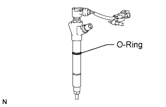 |
Apply a light coat of engine oil to the O-rings on each injector.
Install the 4 injectors to the cylinder head.
- ПРИМЕЧАНИЕ:
- Fit the injectors to the nozzle seats.
Temporarily install the 4 clamps to the cylinder head with the 4 bolts.
 |
Using a hexagon socket wrench, tighten the 4 bolts.
- Момент затяжки:
- 9 Н*м{92 кгс*см, 80 фунт-сила-дюймов}
Install the nozzle holder clamps and washers as shown in the illustration.
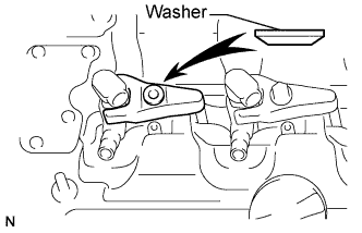 |
Temporarily install the nozzle holder clamp bolts.
- ПРИМЕЧАНИЕ:
- Pay attention to the mounting orientation (bevelled edge) of the washer.
- When temporarily attaching the nozzle holder clamp and the nozzle holder clamp bolt, be careful not to position them at an angle.
- УКАЗАНИЕ:
- Apply a light coat of engine oil to the threads of the nozzle holder clamp bolts.
Temporarily install the No. 1, No. 2, No. 3 and No. 4 injection pipes.
Temporarily install 4 new gaskets and the No. 1 nozzle leakage pipe assembly with the 4 union bolts.
Tighten the 4 nozzle holder clamp bolts.
- Момент затяжки:
- 25 Н*м{255 кгс*см, 18 фунт-сила-футов}
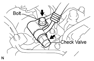
| 24. INSTALL NO. 1 NOZZLE LEAKAGE PIPE ASSEMBLY |
Temporarily install a new gasket, the fuel check valve and bolt.
 |
Tighten the 4 union bolts.
- Момент затяжки:
- 18 Н*м{184 кгс*см, 13 фунт-сила-футов}
 |
Tighten the fuel check valve and bolt.
- Момент затяжки:
- For fuel check valve:
- 32 Н*м{321 кгс*см, 23 фунт-сила-футов}
- For bolt:
- 21 Н*м{209 кгс*см, 15 фунт-сила-футов}
| 25. INSTALL OIL FILLER CAP SUB-ASSEMBLY |
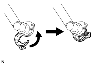
| 26. INSTALL FUEL TUBE SUB-ASSEMBLY |
Turn the retainer in the direction indicated by the arrow until the retainer stops.
 |
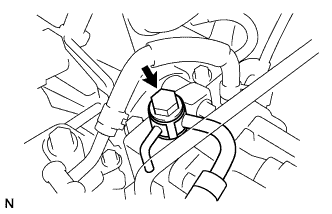
Install the fuel tube sub-assembly and a new gasket with the union bolt.
- Момент затяжки:
- 23 Н*м{235 кгс*см, 17 фунт-сила-футов}
 |
Insert the fuel tube connector into the injector.
 |
Turn the retainer in the direction indicated by the arrow until it makes a "click" sound.
- ПРИМЕЧАНИЕ:
- If the fuel tube connector is not inserted to the correct position of the injector, the retainer cannot be turned further in the direction of the arrow.
 |
Connect the exhaust fuel addition injector connector.
 |
| 27. INSTALL FUEL HOSE PROTECTOR |
Install the fuel hose protector with the bolt.
- Момент затяжки:
- 21 Н*м{210 кгс*см, 15 фунт-сила-футов}
 |
| 28. INSTALL NO. 2 NOZZLE LEAKAGE PIPE |
| 29. INSTALL INJECTION PIPE SUB-ASSEMBLY |
- ПРИМЕЧАНИЕ:
- In a case where an injector is replaced, the injection pipes must also be replaced.
Temporarily install the 4 injection pipes.
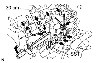 |
Using SST, first tighten the nut at the common rail end of the injection pipe.
- SST
- 09023-38401
- Момент затяжки:
- With SST:
- 27 Н*м{275 кгс*см, 20 фунт-сила-футов}
- Момент затяжки:
- Without SST:
- 30 Н*м{306 кгс*см, 22 фунт-сила-футов}
- УКАЗАНИЕ:
- Use of proper SST is required to ensure that the correct torque is applied to the injection pipe nut.
- Use a torque wrench with a fulcrum length of 30 cm (11.81 in.).
- Make sure that the pipe is not deformed or twisted during installation.
If the pipe is deformed or twisted, or if it cannot be installed properly, replace the pipe with a new one.
Using SST, tighten the nut at the injector end of the injection pipe.
- SST
- 09023-38401
- Момент затяжки:
- With SST:
- 27 Н*м{275 кгс*см, 20 фунт-сила-футов}
- Момент затяжки:
- Without SST:
- 30 Н*м{306 кгс*см, 22 фунт-сила-футов}
- УКАЗАНИЕ:
- Use of proper SST is required to ensure that the correct torque is applied to the injection pipe nut.
- Use a torque wrench with a fulcrum length of 30 cm (11.81 in.).
- Make sure that the pipe is not deformed or twisted during installation.
If the pipe is deformed or twisted, or if it cannot be installed properly, replace the pipe with a new one.
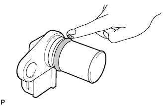
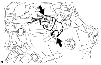
| 30. INSTALL CAMSHAFT POSITION SENSOR |
Apply a light coat of engine oil to the O-ring of the sensor.
 |
Install the sensor with the bolt.
- Момент затяжки:
- 8.8 Н*м{90 кгс*см, 78 фунт-сила-дюймов}
 |
Connect the sensor connector.
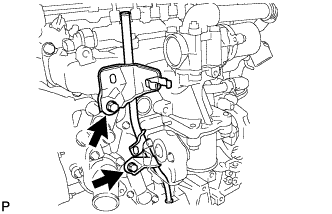
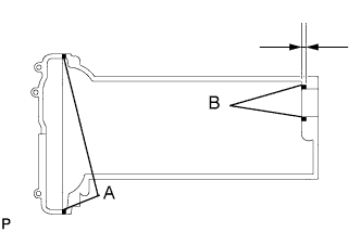
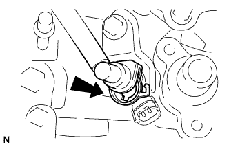
| 31. INSTALL VACUUM PUMP ASSEMBLY |
Нанесите моторное масло на маслопровод на кончике вакуумного насоса в сборе.
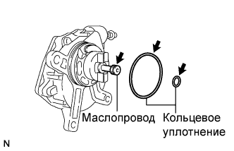 |
Нанесите моторное масло на 2 новых кольцевых уплотнения и установите их на вакуумный насос в сборе.
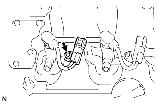
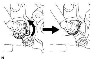
Установите вакуумный насос в сборе таким образом, чтобы соединительный зубец (A) вакуумного насоса в сборе вошел в зацепление с канавкой (B) распредвала.
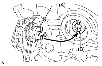 |
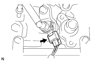
Вверните 3 новых болта.
- Момент затяжки:
- 21 Н*м{214 кгс*см, 15 фунт-сила-футов}
 |
Подсоедините 2 вакуумных шланга и сдвиньте фиксатор.
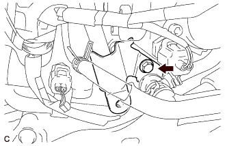
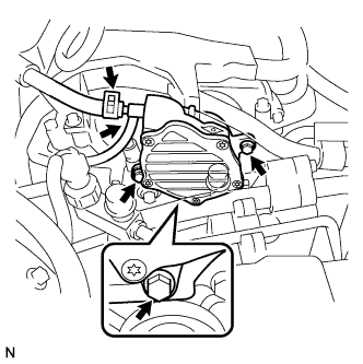
| 32. INSTALL V-RIBBED BELT TENSIONER ASSEMBLY |
Install the tensioner with the 3 bolts.
- Момент затяжки:
- 20 Н*м{204 кгс*см, 15 фунт-сила-футов}
- ПРИМЕЧАНИЕ:
- As the bolts' heads are not as thick as typical bolts, be careful not to damage them during installation.
 |
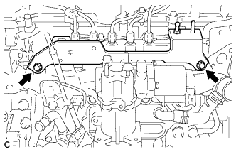
| 33. INSTALL ENGINE MOUNTING BRACKET |
Set the mounting bracket.
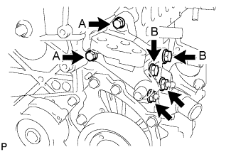 |
Temporarily tighten the 2 bolts (B) and 2 nuts.
Tighten the 2 bolts (A).
- Момент затяжки:
- 28 Н*м{286 кгс*см, 21 фунт-сила-футов}for bolt A
Tighten the 2 bolts (B) and 2 nuts.
- Момент затяжки:
- 80 Н*м{816 кгс*см, 59 фунт-сила-футов}for bolt B
| 34. INSTALL NO. 4 WATER BY-PASS PIPE |
Apply soapy water to a new O-ring and install it to the by-pass pipe.
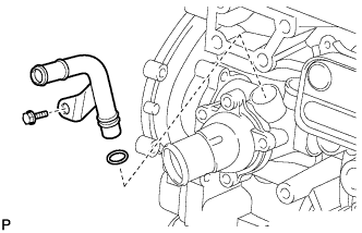 |
Install the No. 4 water by-pass pipe with the bolt.
- Момент затяжки:
- 11 Н*м{112 кгс*см, 8 фунт-сила-футов}
| 35. INSTALL NO. 1 IDLER PULLEY SUB-ASSEMBLY |
Install the idler pulley with the bolt.
- Момент затяжки:
- 40 Н*м{408 кгс*см, 30 фунт-сила-футов}
 |
Install the idler pulley cover plate.
| 36. INSTALL NO. 2 IDLER PULLEY SUB-ASSEMBLY |
Install the idler pulley with the bolt.
- Момент затяжки:
- 40 Н*м{408 кгс*см, 30 фунт-сила-футов}
 |
| 37. INSTALL CRANKSHAFT POSITION SENSOR |
Apply a light coat of engine oil to the O-ring of the sensor.
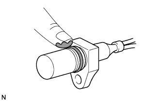 |
Install the sensor with the bolt.
- Момент затяжки:
- 8.8 Н*м{90 кгс*см, 78 фунт-сила-дюймов}
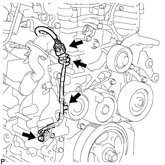 |
Connect the sensor wire harness clamp.
Connect the sensor connector to the bracket.
Connect the sensor connector.
| 38. INSTALL GENERATOR ASSEMBLY |
Install the generator assembly with the 3 bolts.
- Момент затяжки:
- 25 Н*м{255 кгс*см, 18 фунт-сила-футов}
- ПРИМЕЧАНИЕ:
- Make sure that the wire harness of the crankshaft position sensor does not get caught between the cylinder block and the generator assembly when installing the generator assembly.
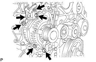 |
Connect the generator wire to terminal B with the nut and bolt.
- Момент затяжки:
- for Nut:
- 9.8 Н*м{100 кгс*см, 87 фунт-сила-дюймов}
- for Bolt:
- 7.7 Н*м{79 кгс*см, 68 фунт-сила-дюймов}
Install the terminal cap.
Connect the generator connector.
| 39. REMOVE ENGINE FROM STAND |
Install the sling device and chain block to the engine and hang the engine.
Remove the engine stand.
| 40. INSTALL ENGINE ASSEMBLY |