Dtc P0504 Корреляция Сигналов Выключателей Тормоза A/B
ОПИСАНИЕ
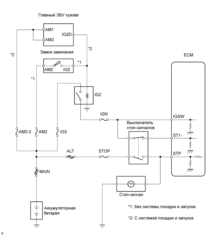
СХЕМА СОЕДИНЕНИЙ
ПОСЛЕДОВАТЕЛЬНОСТЬ ПРОВЕРКИ
ПРОВЕРЬТЕ ВЫКЛЮЧАТЕЛЬ СТОП-СИГНАЛОВ (НАПРЯЖЕНИЕ НА КОНТАКТАХ)
ПРОВЕРЬТЕ ВЫКЛЮЧАТЕЛЬ СТОП-СИГНАЛОВ В СБОРЕ
ПРОВЕРЬТЕ ECM (STP И ST1 - НАПРЯЖЕНИЕ)
ПРОВЕРЬТЕ ПРЕДОХРАНИТЕЛЬ (ПРЕДОХРАНИТЕЛИ STOP И IGN)
DTC P0504 Корреляция сигналов выключателей тормоза "A"/"B" |
ОПИСАНИЕ
Выключатель стоп-сигналов использует дуплексную связь, которая позволяет передавать два сигнала: STP и ST1-. Блок ЕСМ использует эти два сигнала для осуществления контроля за работой тормозной системы. Если сигналы, соответствующие нажатому или отпущенному состоянию педали тормоза, обнаруживаются одновременно, ECM рассматривает это как неисправность выключателя стоп-сигналов и регистрирует DTC.- УКАЗАНИЕ:
- Нормальные состояния приводятся в таблице ниже. Сигналы можно считать с помощью портативного диагностического прибора.
Сигнал
| Педаль тормоза отпущена
| Промежуточное состояние
| Педаль тормоза нажата
|
STP
| OFF (ВЫКЛ)
| ON (ВКЛ)
| ON (ВКЛ)
|
ST1-
| ON (ВКЛ)
| ON (ВКЛ)
| OFF (ВЫКЛ)
|
№ DTC
| Условие обнаружения DTC
| Неисправный участок
|
P504
| Условия (a), (b) и (c) сохраняются в течение не менее 0,5 секунд:
(логика диагностирования за 1 поездку)
(а) Зажигание включено (IG)
(b) Педаль тормоза отпущена
(c) Сигнал STP в состоянии OFF (ВЫКЛ) , если состояние сигнала ST1- – тоже OFF (ВЫКЛ)
| - Короткое замыкание в цепи сигнала выключателя стоп-сигналов
- Выключатель стоп-сигналов
- Предохранитель STOP
- Предохранитель IGN
- ECM
|
СХЕМА СОЕДИНЕНИЙ
ПОСЛЕДОВАТЕЛЬНОСТЬ ПРОВЕРКИ
- УКАЗАНИЕ:
- С помощью портативного диагностического прибора считайте фиксированные параметры. В этих параметрах отражается состояние двигателя на момент обнаружения неисправности. При поиске неисправностей фиксированные параметры позволяют определить, двигался ли автомобиль в момент возникновения неисправности или нет, был ли прогрет двигатель, какой была топливовоздушная смесь (обедненной или обогащенной) и пр.
- Состояния сигнала STP можно проверить с помощью портативного диагностического прибора.
- Подсоедините портативный диагностический прибор к DLC3.
- Включите зажигание (IG) и включите портативный диагностический прибор.
- Выберите следующие элементы меню: Powertrain / Engine and ECT / Data List / Stop Light Switch.
- Проверьте состояние сигнала STP при нажатии и отпускании педали тормоза.
Состояние педали тормоза
| Заданные условия
|
Нажата
| Состояние ON (ВКЛ) сигнала STP
|
Отпущена
| Состояние OFF (ВЫКЛ) сигнала STP
|
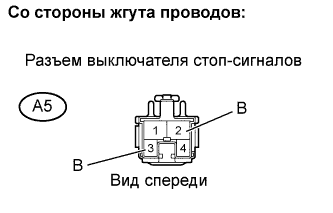
| 1.ПРОВЕРЬТЕ ВЫКЛЮЧАТЕЛЬ СТОП-СИГНАЛОВ (НАПРЯЖЕНИЕ НА КОНТАКТАХ) |
Отсоедините разъем А5 выключателя стоп-сигналов.
Включите зажигание (IG).
Измерьте напряжение между контактами разъема А5 выключателя стоп-сигналов и массой.
- Номинальное напряжение:
Контакты для подключения диагностического прибора
| Заданные условия
|
B (A5-2) - масса
| 9-14 В
|
B (A5-3) - масса
| 9-14 В
|
Подсоедините разъем выключателя стоп-сигналов.
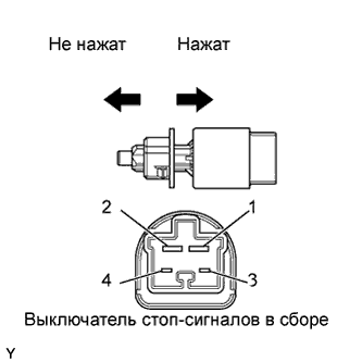
| 2.ПРОВЕРЬТЕ ВЫКЛЮЧАТЕЛЬ СТОП-СИГНАЛОВ В СБОРЕ |
Снимите выключатель стоп-сигналов в сборе.
Измерьте сопротивление.
- Номинальное сопротивление:
Контакты для подключения диагностического прибора
| Положение переключателя
| Заданные условия
|
1 - 2
| Штырь выключателя не нажат
| Менее 1 Ом
|
Штырь выключателя нажат
| 10 кОм или более
|
3 - 4
| Штырь выключателя не нажат
| 10 кОм или более
|
Штырь выключателя нажат
| Менее 1 Ом
|
Установите выключатель стоп-сигналов в сборе на место.
| | ЗАМЕНИТЕ ВЫКЛЮЧАТЕЛЬ СТОП-СИГНАЛОВ В СБОРЕ |
|
|
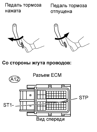
| 3.ПРОВЕРЬТЕ ECM (STP И ST1 - НАПРЯЖЕНИЕ) |
Отсоедините разъем А12 блока ЕСМ.
Включите зажигание (IG).
Измерьте напряжение между контактами ST1- и STP разъема А12 блока ЕСМ и массой.
- Номинальное напряжение:
Контакты для подключения диагностического прибора
| Состояние педали тормоза
| Заданные условия
|
ST1- (A12-35) - масса
| Отпущена
| 9-14 В
|
Нажата
| 0-3 В
|
STP (A12-36) - масса
| Отпущена
| 0-3 В
|
Нажата
| 9-14 В
|
Подсоедините разъем ECM.
| | ОТРЕМОНТИРУЙТЕ ИЛИ ЗАМЕНИТЕ ЖГУТ ПРОВОДОВ ИЛИ РАЗЪЕМ |
|
|
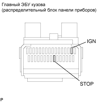
| 4.ПРОВЕРЬТЕ ПРЕДОХРАНИТЕЛЬ (ПРЕДОХРАНИТЕЛИ STOP И IGN) |
Извлеките предохранители STOP и IGN из главного ЭБУ кузова (распределительного блока панели приборов).
Измерьте сопротивление.
- Номинальное сопротивление:
- Менее 1 Ом
Установите предохранители STOP и IGN на место.
| | ПРОВЕРЬТЕ, НЕТ ЛИ КОРОТКОГО ЗАМЫКАНИЯ ВО ВСЕХ ЖГУТАХ ПРОВОДОВ И УСТРОЙСТВАХ, ПОДСОЕДИНИНЕННЫХ К ПРЕДОХРАНИТЕЛЮ |
|
|
| OK |
|
|
|
| ОТРЕМОНТИРУЙТЕ ИЛИ ЗАМЕНИТЕ ЖГУТ ПРОВОДОВ ИЛИ РАЗЪЕМ |
|