Land Cruiser URJ200 URJ202 GRJ200 VDJ200 - SEAT
SEAT HEATER SYSTEM - ON-VEHICLE INSPECTION
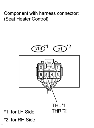
| 1. INSPECT SEAT HEATER CONTROL SUB-ASSEMBLY (for Front Side) |

Disconnect the c13 and c1 heater control connectors.
Measure the resistance according to the value(s) in the table below.
- Standard Resistance:
for LH Side Tester Connection Specified Condition c13-6 (E) - Body ground Below 1 Ω for RH Side Tester Connection Specified Condition c1-6 (E) - Body ground Below 1 Ω
If the result is not as specified, there may be a malfunction on the wire harness side.
Measure the voltage according to the value(s) in the table below.
- Standard Voltage:
for LH Side Tester Connection Switch Condition Specified Condition c13-1 (SWL) - c13-6 (E) Engine switch on (IG), seat heater switch off Below 1 V Engine switch on (IG), seat heater switch on 11 to 14 V c13-4 (B) - c13-6 (E) Engine switch off Below 1 V Engine switch on (IG) 11 to 14 V for RH Side Tester Connection Switch Condition Specified Condition c1-1 (SWR) - c1-6 (E) Engine switch on (IG), seat heater switch off Below 1 V Engine switch on (IG), seat heater switch on 11 to 14 V c1-4 (B1) - c1-6 (E) Engine switch off Below 1 V Engine switch on (IG) 11 to 14 V
If the result is not as specified, there may be a malfunction on the wire harness side.
Connect the c13 and c1 heater control connectors.
Measure the voltage according to the value(s) in the table below.
- Standard Voltage:
for LH Side Tester Connection Switch Condition Specified Condition c13-5 (THL) - Body ground Engine switch on (IG), seat heater switch on, volume Min→ Max Gradual increase from below 1 V to 11 to 14 V for RH Side Tester Connection Switch Condition Specified Condition c1-5 (THR) - Body ground Engine switch on (IG), seat heater switch on, volume Min → Max Gradual increase from below 1 V to 11 to 14 V
If the result is not as specified, the seat heater control may have a malfunction.