Стартер -- Проверка |
| 1. INSPECT STARTER ASSEMBLY |
- ПРИМЕЧАНИЕ:
- The following tests must not be performed continuously for longer than 5 seconds to prevent the coil from burning out.
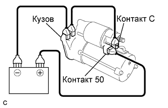
Perform a pull-in test.
Remove the nut and disconnect the lead wire from terminal C.
Connect the battery to the magnet starter switch as shown in the illustration. Check that the clutch pinion gear is extended.
If the clutch pinion gear does not move, replace the magnet starter switch assembly.
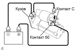
Perform a hold-in test.
Disconnect the negative (-) lead from terminal C. Check that the clutch pinion gear remains extended.
If the clutch pinion gear returns inward, replace the magnet starter switch assembly.
 |
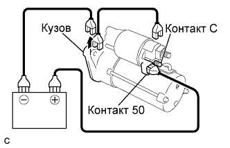
Check the operation.
Disconnect the negative (-) lead from the switch body. Check that the clutch pinion gear returns.
If the clutch pinion gear does not return inward, replace the magnet starter switch assembly.
 |
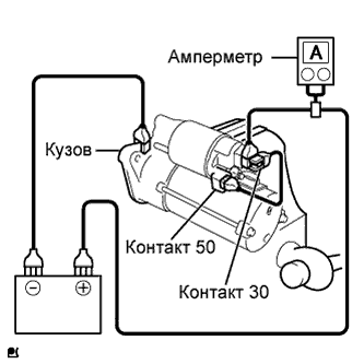
Perform a no-load performance test.
Connect the lead wire to terminal C. Make sure that the lead is not grounded.
- Момент затяжки:
- 9.8 Н*м{100 кгс*см, 87 фунт-сила-дюймов}
Clamp the starter in a vise.
Connect the battery and an ammeter to the starter as shown in the illustration.
Check that the starter rotates smoothly and steadily with the clutch pinion gear extended. Check that the ammeter reads the specified current.
- Standard current:
Tester Connection Condition Specified Condition Battery positive terminal - Terminal 30 - Terminal 50 11.5 V Below 90 A
| 2. INSPECT STARTER ARMATURE ASSEMBLY |
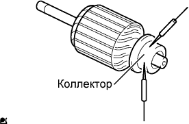
Check the commutator for open circuits.
Using an ohmmeter, measure the resistance between the segments of the commutator.
- Standard resistance:
Tester Connection Condition Specified Condition Segment - Segment - Below 1 Ω
 |
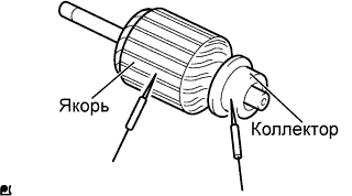
Check the commutator for ground.
Using an ohmmeter, measure the resistance between the commutator and the armature core.
- Standard resistance:
Tester Connection Condition Specified Condition Commutator - Armature core - 10 kΩ or higher
 |
Check the commutator surface for dirt and burns.
If the surface is dirty or burnt, restore it with sandpaper (No. 400) or a lathe.
Check the commutator for circle runout.
Place the commutator on V-blocks.
Using a dial indicator, measure the circle runout.
- Maximum runout:
- 0.05 mm (0.0020 in.)
 |
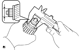
Using vernier calipers, measure the commutator diameter.
- Standard diameter:
- 28.0 mm (1.1024 in.)
- Minimum diameter:
- 27.0 mm (1.0630 in.)
 |
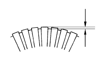
Check that the undercut portion between the segments is free of foreign matter and measure its depth.
- Standard undercut depth:
- 0.6 mm (0.0236 in.)
- Minimum undercut depth:
- 0.2 mm (0.0079 in.)
 |
| 3. INSPECT STARTER YOKE ASSEMBLY |
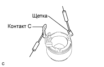
Using an ohmmeter, measure the resistance between terminal C and the field coil brush lead.
- Standard resistance:
Tester Connection Condition Specified Condition Terminal C - Brush lead - Below 1 Ω
 |
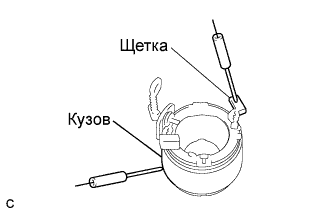
Using an ohmmeter, measure the resistance between the brush lead and the body.
- Standard resistance:
Tester Connection Condition Specified Condition Brush lead - Body - 10 kΩ or higher
 |
| 4. INSPECT BRUSH |
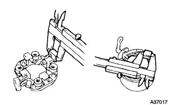
Using vernier calipers, measure the brush length.
- Standard length:
- 14 mm (0.5511 in.)
- Minimum length:
- 9 mm (0.3543 in.)
 |
| 5. INSPECT STARTER BRUSH HOLDER ASSEMBLY |
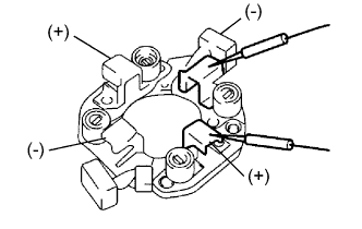
Using an ohmmeter, measure the resistance between the positive (+) and negative (-) brush holders.
- Standard resistance:
Tester Connection Condition Specified Condition Positive brush holder - Negative brush holder - 10 kΩ or higher
 |
| 6. INSPECT STARTER CLUTCH SUB-ASSEMBLY |
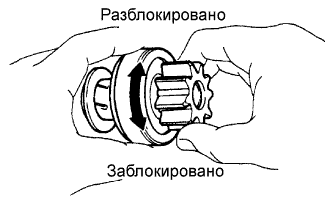 |
Hold the starter clutch and rotate the pinion gear clockwise, and check that it turns freely. Try to rotate the pinion gear counterclockwise and check that it locks.
If necessary, replace the starter clutch sub-assembly.
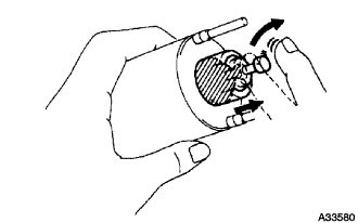
| 7. INSPECT MAGNET STARTER SWITCH ASSEMBLY |
Check the plunger.
Push in the plunger and check that it returns quickly to its original position.
If necessary, replace the magnet starter switch assembly.- ПРИМЕЧАНИЕ:
- To avoid damaging the inside of the magnet starter switch, do not release the plunger quickly.
 |
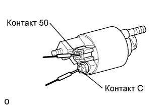
Check the pull-in coil for open circuits.
Using an ohmmeter, measure the resistance between terminals 50 and C.
- Standard resistance:
Tester Connection Condition Specified Condition Terminal 50 - Terminal C - Below 1 Ω
 |
Check whether the holding coil has an open circuit.
Using an ohmmeter, measure the resistance between terminal 50 and the switch body.
- Standard resistance:
Tester Connection Condition Specified Condition Terminal 50 - Body - Below 2 Ω
 |